Nissan Sentra Service Manual: P0182, P0183 FTT Sensor
DTC Logic
DTC DETECTION LOGIC
| DTC No. | CONSULT screen terms (Trouble diagnosis content) | DTC detecting condition | Possible cause |
| P0182 | FTT SEN/CIRCUIT (Fuel temperature sensor ″A″ circuit low) | An excessively low voltage from the sensor is sent to ECM. |
|
| P0183 | FTT SEN/CIRCUIT (Fuel temperature sensor ″A″ circuit high) | An excessively high voltage from the sensor is sent to ECM. |
DTC CONFIRMATION PROCEDURE
1.PRECONDITIONING
If DTC Confirmation Procedure has been previously conducted, always perform the following procedure before conducting the next test.
- Turn ignition switch OFF and wait at least 10 seconds.
- Turn ignition switch ON.
- Turn ignition switch OFF and wait at least 10 seconds.
>> GO TO 2.
2.PERFORM DTC CONFIRMATION PROCEDURE
- Turn ignition switch ON and wait at least 5 seconds.
- Check 1st trip DTC.
Is 1st trip DTC detected? YES >> Proceed to EC-258, "Diagnosis Procedure".
NO >> INSPECTION END
Diagnosis Procedure
1.CHECK DTC WITH COMBINATION METER
Refer to MWI-17, "CONSULT Function (METER/M&A)".
Is the inspection result normal? YES >> GO TO 2.
NO >> Proceed to MWI-58, "Diagnosis Procedure".
2.CHECK FUEL TANK TEMPERATURE (FTT) SENSOR POWER SUPPLY
- Turn ignition switch OFF.
- Disconnect fuel level sensor unit and fuel pump harness connector.
- Turn ignition switch ON.
- Check the voltage between fuel level sensor unit and fuel pump harness connector and ground.
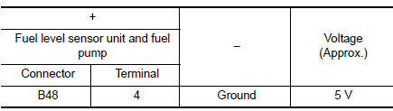
Is the inspection result normal? YES >> GO TO 4.
NO >> GO TO 3.
3.CHECK FUEL TANK TEMPERATURE (FTT) SENSOR POWER SUPPLY CIRCUIT
- Turn ignition switch OFF.
- Disconnect ECM harness connector.
- Check the continuity between fuel level sensor unit and fuel pump harness connector and ECM harness connector.
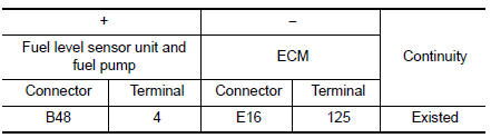
- Also check harness for short to ground and to power.
Is the inspection result normal? YES >> Perform the trouble diagnosis for power supply circuit.
NO >> Repair or replace error-detected parts.
4.CHECK FUEL TANK TEMPERATURE (FTT) SENSOR GROUND CIRCUIT
- Turn ignition switch OFF.
- Disconnect ECM connector.
- Check the continuity between fuel level sensor unit and fuel pump harness connector and ECM harness connector.
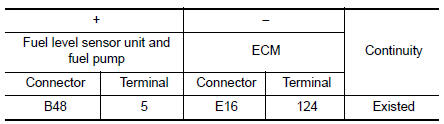
- Also check harness for short to power.
Is the inspection result normal? YES >> GO TO 5.
NO >> Repair or replace error-detected parts.
5.CHECK FUEL TANK TEMPERATURE (FTT) SENSOR
Check the FTT sensor. Refer to EC-259, "Component Inspection".
Is the inspection result normal? YES >> Check intermittent incident. Refer to GI-39, "Intermittent Incident".
NO >> Replace “fuel level sensor unit and fuel pump”. Refer to FL-6, "Removal and Installation".
Component Inspection
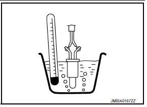
1.CHECK FUEL TANK TEMPERATURE (FTT) SENSOR
- Turn ignition switch OFF.
- Disconnect fuel level sensor unit and fuel pump harness connector.
- Remove fuel level sensor unit. Refer to FL-6, "Removal and Installation".
- Check resistance between fuel level sensor unit and fuel pump terminals by heating with hot water as shown in the figure.
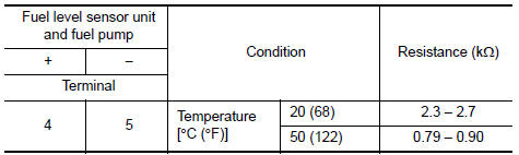
Is the inspection result normal? YES >> INSPECTION END
NO >> Replace fuel level sensor unit and fuel pump. Refer to FL-6, "Removal and Installation".
 P0181 FTT Sensor
DTC Logic
DTC DETECTION LOGIC
DTC No.
CONSULT screen terms
(Trouble diagnosis content)
DTC detecting condition
Possible cause
P0181
FTT SENSOR
(Fuel temperature sen ...
 P0196 EOT Sensor
DTC Logic
DTC DETECTION LOGIC
NOTE:
If DTC P0196 is displayed with DTC P0197 or P0198, first perform the
trouble diagnosis for DTC P0197 or
P0198. Refer to EC-264, "DTC Logic".
...
Other materials:
Fuel pump
Component Function Check
1.CHECK FUEL PUMP FUNCTION
Turn ignition switch ON.
Pinch fuel feed hose with
two fingers.
Fuel pressure pulsation should be felt on the fuel feed
hose for 1 second after ignition switch is turned ON.
Is the inspection result normal?
YES >> INSPECT ...
To protect your vehicle from corrosion
Wash and wax your vehicle often to keep the
vehicle clean.
Always check for minor damage to the paint
and repair it as soon as possible.
Keep drain holes at the bottom of the doors
open to avoid water accumulation.
Check the underbody for accumulation of
sand, dirt or salt. If prese ...
Combination switch
Exploded view
Combination switch
Combination switch harness connector
Front
NOTE:
Shown with the steering wheel removed for clarity only.
Removal and installation
REMOVAL
CAUTION:
Before servicing, turn the ignition switch OFF, disconnect both
battery terminals and wait at l ...
