Nissan Sentra Service Manual: Fuel pump
Component Function Check
1.CHECK FUEL PUMP FUNCTION
- Turn ignition switch ON.
- Pinch fuel feed hose
 with
with
two fingers.
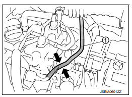
Fuel pressure pulsation should be felt on the fuel feed hose for 1 second after ignition switch is turned ON.
Is the inspection result normal? YES >> INSPECTION END
NO >> Proceed to EC-453, "Diagnosis Procedure".
Diagnosis Procedure
1.CHECK FUEL PUMP POWER SUPPLY CIRCUIT-1
- Turn ignition switch OFF.
- Disconnect ECM harness connector.
- Turn ignition switch ON.
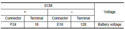
- Check the voltage between ECM harness connector and ground.
Is the inspection result normal? YES >> GO TO 3.
NO >> GO TO 2.
2.CHECK FUEL PUMP POWER SUPPLY CIRCUIT-2
- Turn ignition switch OFF.
- Disconnect IPDM E/R harness connector.
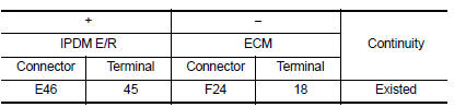
- Check the continuity between IPDM E/R harness connector and ECM harness connector.
- Also check harness for short to ground and short to power.
Is the inspection result normal? YES >> GO TO 8.
NO >> Repair or replace error-detected parts.
3.CHECK FUEL PUMP POWER SUPPLY CIRCUIT-3
- Turn ignition switch OFF.
- Reconnect all harness connectors disconnected.
- Disconnect fuel pump harness connector.
- Turn ignition switch ON.
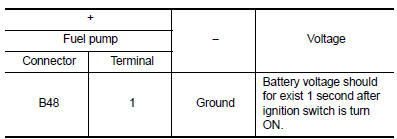
- Check the voltage between fuel pump harness connector and ground.
Is the inspection result normal? YES >> GO TO 6.
NO >> GO TO 4.
4.CHECK FUSE
- Turn ignition switch OFF.
- Disconnect 15A fuse (No. 50) from IPDM E/R.
- Check 15A fuse.
Is the inspection result normal? YES >> GO TO 5.
NO >> Replace 15A fuse.
5.CHECK FUEL PUMP POWER SUPPLY CIRCUIT-4
- Turn ignition switch OFF.
- Disconnect IPDM E/R harness connector
- Check the continuity between IPDM E/R harness connector and fuel pump harness connector.
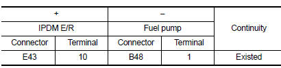
- Also check harness for short to ground and short to power.
Is the inspection result normal? YES >> GO TO 6.
NO >> Repair or replace error-detected parts.
6.CHECK FUEL PUMP GROUND CIRCUIT
- Turn ignition switch OFF.
- Check the continuity between fuel pump harness connector and ground.
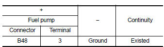
- Also check harness for short to power.
Is the inspection result normal? YES >> GO TO 7.
NO >> Repair or replace error-detected parts.
7.CHECK FUEL PUMP
Check fuel pump. Refer to EC-455, "Component Inspection (Fuel Pump)".
Is the inspection result normal? YES >> GO TO 8.
NO >> Replace fuel filter and fuel pump. Refer to FL-6, "Exploded View".
8.CHECK INTERMITTENT INCIDENT
Check intermittent incident. Refer to GI-39, "Intermittent Incident".
Is the inspection result normal? YES >> Replace IPDM E/R. Refer to PCS-30, "Removal and Installation" (With intelligent key) or PCS-58, "Removal and Installation" (Without intelligent key).
NO >> Repair or replace error-detected parts.
Component Inspection (Fuel Pump)
1.CHECK FUEL PUMP
- Turn ignition switch OFF
- Disconnect fuel level sensor unit and fuel pump harness connector.
- Check resistance between fuel pump terminals as follows.
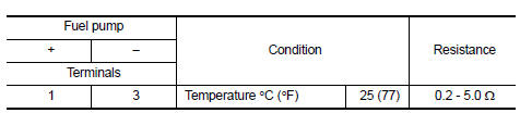
Is the inspection result normal? YES >> INSPECTION END
NO >> Replace fuel filter and fuel pump. Refer to FL-6, "Removal and Installation".
 Fuel injector
Component Function Check
1.INSPECTION START
Turn ignition switch to START.
Is any cylinder ignited?
YES >> GO TO 2.
NO >> Proceed to EC-450, "Diagnosis Procedure".
2.CH ...
 Ignition signal
Component Function Check
1.INSPECTION START
Turn ignition switch OFF.
Start engine.
Does the engine start?
YES >> GO TO 2.
NO >> Proceed to EC-456, "Diagnosis Procedure& ...
Other materials:
Precaution for Work
When removing or disassembling each component, be careful not to damage
or deform it. If a component
may be subject to interference, be sure to protect it with a shop cloth.
When removing (disengaging) components with a screwdriver or similar
tool, be sure to wrap the component
with a ...
Warning lights
Anti-lock
Braking
System (ABS) warning light
When the ignition switch is placed in the ON
position, the Anti-lock Braking System (ABS)
warning light illuminates and then turns off. This
indicates the ABS is operational.
If the ABS warning light illuminates while the
engine is running or ...
Symptom diagnosis
Squeak and rattle trouble diagnoses
Work Flow
CUSTOMER INTERVIEW
Interview the customer if possible, to determine the conditions that exist
when the noise occurs. Use the Diagnostic
Worksheet during the interview to document the facts and conditions when the
noise occurs and any
custome ...
