Nissan Sentra Service Manual: Ignition signal
Component Function Check
1.INSPECTION START
- Turn ignition switch OFF.
- Start engine.
Does the engine start? YES >> GO TO 2.
NO >> Proceed to EC-456, "Diagnosis Procedure".
2.IGNITION SIGNAL FUNCTION
 With CONSULT
- Perform “POWER BALANCE” in “ACTIVE TEST” mode of “ENGINE” using CONSULT.
- Check that each circuit produces a momentary engine speed drop.
 Without CONSULT
- Let engine idle.
- Check the voltage signal between ECM harness connector and ground with an oscilloscope.
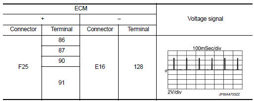
NOTE:
The pulse cycle changes depending on rpm at idle.
Is the inspection result normal? YES >> INSPECTION END
NO >> Proceed to EC-456, "Diagnosis Procedure".
Diagnosis Procedure
1.CHECK FUSE
- Turn ignition switch OFF.
- Pull out #51 fuse and check that the fuse is not fusing.
Is the inspection result normal? YES >> GO TO 2.
NO >> Replace the fuse after repairing the applicable circuit.
2.CHECK IGNITION COIL POWER SUPPLY
- Insert the fuse which pulled out.
- Disconnect ignition coil harness connector
- Turn ignition switch ON.
- Check the voltage between ignition coil harness connector and ground.
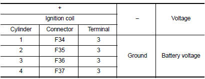
Is the inspection result normal? YES >> GO TO 4.
NO >> GO TO 3.
3.CHECK IGNITION COIL POWER SUPPLY CIRCUIT
- Turn ignition switch OFF.
- Disconnect IPDM E/R harness connector
- Check the continuity between IPDM E/R harness connector and ignition coil harness connector.
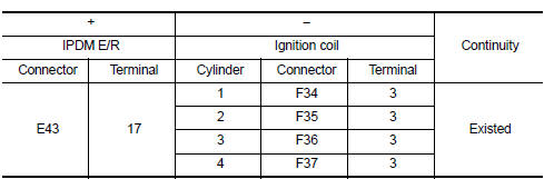
- Also check harness for short to ground.
Is the inspection result normal? YES >> Check intermittent incident. Refer to GI-39, "Intermittent Incident".
NO >> Repair or replace error-detected parts.
4.CHECK IGNITION COIL GROUND CIRCUIT
- Turn ignition switch OFF.
- Check the continuity between ignition coil harness connector and ground
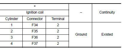
- Also check harness for short to power.
Is the inspection result normal? YES >> GO TO 5.
NO >> Repair or replace error-detected parts.
5.CHECK IGNITION COIL OUTPUT SIGNAL CIRCUIT
- Disconnect ECM harness connector.
- Check the continuity between ECM harness connector and ignition coil harness connector.
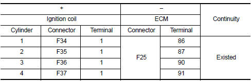
- Also check harness for short to ground and short to power.
Is the inspection result normal? YES >> GO TO 6.
NO >> Repair or replace error-detected parts.
6.CHECK IGNITION COIL WITH POWER TRANSISTOR
Check ignition coil with power transistor. Refer to EC-459, "Component Inspection (Ignition Coil with Power Transistor)".
Is the inspection result normal? YES >> GO TO 7.
NO >> Replace malfunctioning ignition coil with power transistor. Refer to EM-45, "Exploded View".
7.CHECK CONDENSER CIRCUIT
- Turn ignition switch OFF.
- Disconnect condenser.
- Disconnect IPDM E/R harness connector.
- Check the continuity between IPDM E/R harness connector and condenser harness connector.
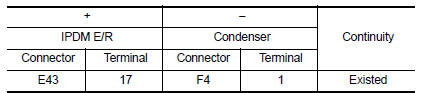
- Also check harness for short to ground.
Is the inspection result normal? YES >> GO TO 8.
NO >> Repair or replace error-detected parts.
8.CHECK CONDENSER GROUND CIRCUIT
- Check the continuity between Condenser harness connector and ground.
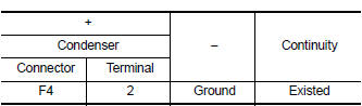
- Also check harness for short to power.
Is the inspection result normal? YES >> GO TO 9.
NO >> Repair or replace error-detected parts.
9.CHECK CONDENSER
Check condenser. Refer to EC-459, "Component Inspection (Condenser)".
Is the inspection result normal? YES >> INSPECTION END
NO >> Replace condenser.
Component Inspection (Condenser)
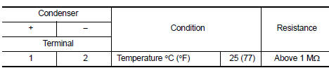
1.CHECK CONDENSER
- Turn ignition switch OFF.
- Disconnect condenser harness connector.
- Check resistance between condenser terminals as per the following.
Is the inspection result normal? YES >> INSPECTION END
NO >> Replace Condenser
Component Inspection (Ignition Coil with Power Transistor)
1.CHECK IGNITION COIL WITH POWER TRANSISTOR-1
- Turn ignition switch OFF.
- Disconnect ignition coil harness connector.
- Check resistance between ignition coil terminals as per the following.
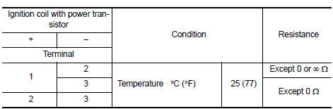
Is the inspection result normal? YES >> GO TO 2.
NO >> Replace malfunctioning ignition coil with power transistor. Refer to EM-45, "Exploded View".
2.CHECK IGNITION COIL WITH POWER TRANSISTOR-2
CAUTION:
Do the following procedure in the place where ventilation is good without the combustible.
- Turn ignition switch OFF.
- Reconnect all harness connectors disconnected.
- Remove fuel pump fuse in IPDM E/R to release fuel pressure.
NOTE:
Do not use CONSULT to release fuel pressure, or fuel pressure applies again during the following procedure.
- Start engine.
- After engine stalls, crank it two or three times to release all fuel pressure.
- Turn ignition switch OFF.
- Remove all ignition coil harness connectors to avoid the electrical discharge from the ignition coils. Refer to EM-45, "Exploded View".
- Remove ignition coil and spark plug of the cylinder to be checked. Refer to EM-45, "Exploded View".
- Crank engine for 5 seconds or more to remove combustion gas in the cylinder.
- Connect spark plug and harness connector to ignition coil.
- Fix ignition coil using a rope etc. with gap of 13 - 17 mm (0.52 - 0.66 in) between the edge of the spark plug and grounded metal portion as shown in the figure.
- Crank engine for about three seconds, and check whether spark is generated between the spark plug and the grounded metal portion.
Spark should be generated.
CAUTION:
During the operation, always stay 0.5 cm (19.7 in) away from the spark plug and the ignition coil. Be careful not to get an electrical shock while checking, because the electrical discharge voltage becomes 20 kV or more.
It might cause to damage the ignition coil if the gap of more than 17 mm (0.66 in) is taken.
NOTE:
When the gap is less than 13 mm (0.52 in), the spark might be generated even if the coil is malfunctioning.
Is the inspection result normal? YES >> INSPECTION END
NO >> Replace malfunctioning ignition coil with power transistor. Refer to EM-45, "Exploded View".
 Fuel pump
Component Function Check
1.CHECK FUEL PUMP FUNCTION
Turn ignition switch ON.
Pinch fuel feed hose with
two fingers.
Fuel pressure pulsation should be felt on the fuel feed
hose for ...
 Electrical load signal
Description
The electrical load signal (Headlamp switch signal, rear window defogger
switch signal, etc.) is transferred via
the CAN communication line.
Component Function Check
1.CHECK REAR WIN ...
Other materials:
On Board Diagnostic (OBD) System of Engine and CVT
The ECM has an on board diagnostic system. It will light up the malfunction
indicator lamp (MIL) to warn the
driver of a malfunction causing emission deterioration.
CAUTION:
Be sure to turn the ignition switch OFF and disconnect the
negative battery cable before any repair
or inspection ...
Wiring diagram
Power distribution system
Wiring diagram
...
Brake precautions
Vacuum assisted brakes
The brake booster aids braking by using engine
vacuum. If the engine stops, you can stop the
vehicle by depressing the brake pedal. However,
greater foot pressure on the brake pedal will be
required to stop the vehicle and stopping distance
will be longer.
Using the bra ...
