Nissan Sentra Service Manual: Electrical load signal
Description
The electrical load signal (Headlamp switch signal, rear window defogger switch signal, etc.) is transferred via the CAN communication line.
Component Function Check
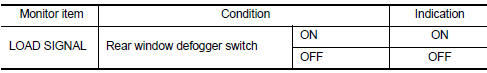
1.CHECK REAR WINDOW DEFOGGER SWITCH FUNCTION
 With CONSULT
- Turn ignition switch ON.
- Select “DATA MONITOR” mode of “ENGINE” using CONSULT.
- Select “LOAD SIGNAL” and check indication as per the following conditions.
Is the inspection result normal? YES >> GO TO 2.
NO >> Proceed to EC-461, "Diagnosis Procedure".
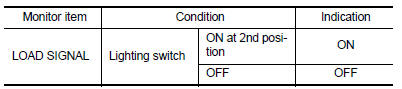
2.CHECK LIGHTING SWITCH FUNCTION
 With CONSULT
Check “LOAD SIGNAL” indication as per the following conditions.
Is the inspection result normal? YES >> GO TO 3.
NO >> Proceed to EC-461, "Diagnosis Procedure".
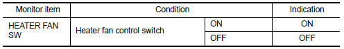
3.CHECK HEATER FAN CONTROL SWITCH FUNCTION
 With CONSULT
Select “HEATER FAN SW” and check indication as per the following conditions.
Is the inspection result normal? YES >> INSPECTION END
NO >> Proceed to EC-461, "Diagnosis Procedure".
Diagnosis Procedure
1.INSPECTION START
Confirm the malfunctioning circuit (rear window defogger, headlamp or heater fan). Refer to EC-461, "Component Function Check".
Which circuit is related to the incident? Rear window defogger>>GO TO 2.
Headlamp>>GO TO 3.
Heater fan>>GO TO 4.
2.CHECK REAR WINDOW DEFOGGER SYSTEM
Check the rear window defogger system. Refer to DEF-27, "Work Flow".
>> INSPECTION END
3.CHECK HEADLAMP SYSTEM
Check the headlamp system. Refer to EXL-85, "Work Flow".
>> INSPECTION END
4.CHECK HEATER FAN CONTROL SYSTEM
Check the heater fan control system. Refer to HA-15, "Workflow".
>> INSPECTION END
 Ignition signal
Component Function Check
1.INSPECTION START
Turn ignition switch OFF.
Start engine.
Does the engine start?
YES >> GO TO 2.
NO >> Proceed to EC-456, "Diagnosis Procedure& ...
 Cooling fan
Component Function Check
1.CHECK COOLING FAN FUNCTION
With CONSULT
Turn ignition switch ON.
Perform “FAN” in “ACTIVE TEST” mode of “ENGINE” using CONSULT
Check ...
Other materials:
Windshield wiper and washer switch
Switch operation
Type A
Type B
The windshield wiper and washer operates when
the ignition switch is placed in the ON position.
Push the lever down to operate the wiper at the
following speed:
Intermittent (INT) — intermittent operation
can be adjusted by turning the knob A .
Lo ...
Engine assembly CVT
CVT : Exploded View
Washer
Upper torque rod (RH)
Engine mounting insulator (RH)
Engine mounting insulator (LH)
Rear torque rod bracket
Rear torque rod
CVT : Removal and Installation
WARNING:
Situate the vehicle on a flat and solid surface.
Place chocks at front and back o ...
Rear seat
Exploded View
Rear seatback assembly (RH)
Seatback striker
Seatback latch release knob
Seatback latch assembly
Seatback silencer (RH)
Rear seatback frame (RH)
Seatback latch release knob finisher
Rear seat bolster trim (RH)
Rear seat bolster pad (RH)
Rear seat bolster (RH)
...
