Nissan Sentra Service Manual: P0117, P0118 ECT Sensor
DTC Logic
DTC DETECTION LOGIC
| DTC No. | CONSULT screen terms (Trouble diagnosis content) | DTC detecting condition | Possible cause |
| P0117 | ECT SEN/CIRC (Engine coolant temperature sensor 1 circuit low) | An excessively low voltage from the engine coolant temperature sensor is sent to ECM. |
|
| P0118 | ECT SEN/CIRC (Engine coolant temperature sensor 1 circuit high) | An excessively high voltage from the engine coolant temperature sensor is sent to ECM. |
DTC CONFIRMATION PROCEDURE
1.PRECONDITIONING
If DTC Confirmation Procedure has been previously conducted, always perform the following procedure before conducting the next test.
- Turn ignition switch OFF and wait at least 10 seconds.
- Turn ignition switch ON.
- Turn ignition switch OFF and wait at least 10 seconds.
>> GO TO 2.
2.PERFORM DTC CONFIRMATION PROCEDURE
- Turn ignition switch ON and wait at least 5 seconds.
- Check DTC.
Is DTC detected? YES >> Proceed to EC-198, "Diagnosis Procedure".
NO >> INSPECTION END
Diagnosis Procedure
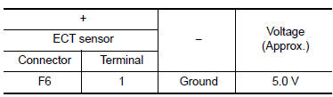
1.CHECK ENGINE COOLANT TEMPERATURE SENSOR POWER SUPPLY
- Turn ignition switch OFF.
- Disconnect engine coolant temperature (ECT) sensor harness connector.
- Turn ignition switch ON.
- Check the voltage between ECT sensor harness connector and ground.
Is the inspection result normal? YES >> GO TO 3.
NO >> GO TO 2.
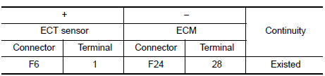
2.CHECK ENGINE COOLANT TEMPERATURE SENSOR POWER SUPPLY CIRCUIT
- Turn ignition switch OFF.
- Disconnect ECM harness connector.
- Check the continuity between ECT sensor harness connector and ECM harness connector.
- Also check harness for short to ground.
Is the inspection result normal? YES >> Perform the trouble diagnosis for power supply circuit.
NO >> Repair or replace error-detected parts.
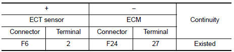
3.CHECK ENGINE COOLANT TEMPERATURE SENSOR GROUND CIRCUIT
- Turn ignition switch OFF.
- Disconnect ECM harness connector.
- Check the continuity between ECT sensor harness connector and ECM harness connector.
- Also check harness for short to ground to power.
Is the inspection result normal? YES >> GO TO 4.
NO >> Repair or replace error-detected parts.
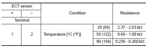
4.CHECK ENGINE COOLANT TEMPERATURE SENSOR
Check the engine coolant temperature sensor. Refer to EC-199, "Component Inspection (ECT Sensor)".
Is the inspection result normal? YES >> Check intermittent incident. Refer to GI-39, "Intermittent Incident".
NO >> Replace engine coolant temperature sensor. Refer to CO-24, "Exploded View".
Component Inspection (ECT Sensor)
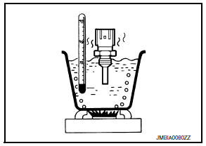
1.CHECK ENGINE COOLANT TEMPERATURE SENSOR
- Turn ignition switch OFF.
- Disconnect engine coolant temperature sensor harness connector.
- Remove engine coolant temperature sensor.
- Check resistance between engine coolant temperature sensor terminals by heating with hot water as shown in the figure.
Is the inspection result normal? YES >> INSPECTION END
NO >> Replace engine coolant temperature sensor. Refer to CO-24, "Exploded View".
 P0116 ECT Sensor
DTC Logic
DTC DETECTION LOGIC
DTC No.
CONSULT screen terms
(Trouble diagnosis content)
DTC detecting condition
Possible cause
P0116
ECT SEN/CIRC
(Engine coolant tem ...
 P0122, P0123 TP Sensor
DTC Logic
DTC DETECTION LOGIC
NOTE:
If DTC P0122 or P0123 is displayed with DTC P0643, first perform the
trouble diagnosis for DTC P0643.
Refer to EC-353, "DTC Logic".
DTC No ...
Other materials:
Diagnosis system (ipdm e/r) (without intelligent key system)
Diagnosis Description
AUTO ACTIVE TEST
Description
In auto active test, the IPDM E/R sends a drive signal to the following
systems to check their operation.
Front wiper (LO, HI)
Parking lamp
License plate lamp
Tail lamp
Front fog lamp (if equipped)
Headlamp (LO, HI)
A/C compress ...
Text messaging
WARNING
Laws in some jurisdictions may restrict
the use of some of the applications and
features, such as social networking and
texting.
Laws in some jurisdictions may restrict
the use of “Text-to-Speech”. Check local
regulations before using this
feature.
...
DTC/circuit diagnosis
U1000 CAN COMM CIRCUIT
Description
Refer to lan-7, "can communication system : system description".
Dtc logic
Dtc detection logic
Note:
U1000 can be set if a module harness was disconnected and reconnected,
perhaps during a repair. Confirm
that there are actual CAN diagnostic symp ...
