Nissan Sentra Service Manual: Main line between ipdm-e and dlc circuit
Diagnosis procedure
1.Check connector
- Turn the ignition switch OFF.
- Disconnect the battery cable from the negative terminal.
- Check the following terminals and connectors for damage, bend and loose connection (connector side and harness side).
- Harness connector E4
- Harness connector M2
Is the inspection result normal? Yes >> go to 2.
No >> repair the terminal and connector.
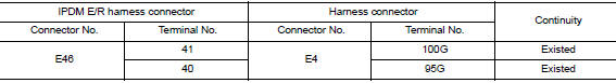
2.Check harness continuity (open circuit)
- Disconnect the following harness connectors.
- Ipdm e/r
- Harness connectors e4 and m2
- Check the continuity between the ipdm e/r harness connector and the harness connector.
Is the inspection result normal? Yes >> go to 3.
No >> repair the main line between the ipdm e/r and the harness connector e4.
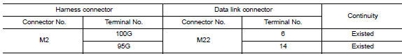
3.Check harness continuity (open circuit)
Check the continuity between the harness connector and the data link connector.
Is the inspection result normal? Yes (present error)>>check can system type decision again.
Yes (past error)>>error was detected in the main line between the ipdm e/r and the data link connector.
No >> repair the main line between the harness connector m2 and the data link connector.
 Can system (type 1)
Dtc/circuit diagnosis ...
 Ecm branch line circuit
Diagnosis procedure
1.Check connector
Turn the ignition switch off.
Disconnect the battery cable from the negative terminal.
Check the terminals and connectors of the ecm for damage, bend and ...
Other materials:
Diagnosis and repair work flow
Work flow
OVERALL SEQUENCE
DETAILED FLOW
1.INTERVIEW THE CUSTOMER FOR THE SYMPTOM
Interview the customer for the symptom (the condition and the environment
when the incident/malfunction
occurs).
>> GO TO 2.
2.CHECK SYMPTOM
Check the symptom from the customer information.
> ...
Sensor power supply 2 circuit
Description
ECM supplies a voltage of 5.0 V to some of the sensors systematically divided
into 2 groups, respectively.
Accordingly, when a short circuit develops in a sensor power source, a
malfunction may occur simultaneously
in the sensors belonging to the same group as the shorted-circui ...
U1010 Control unit (CAN)
Description
Initial diagnosis of ABS actuator and electric unit (control
unit)
DTC Logic
DTC DETECTION LOGIC
DTC
Items
(CONSULT screen terms)
DTC detection condition
Possible cause
U1010
CONTROL UNIT (CAN)
When detecting error during the initial diagnosis
...
