Nissan Sentra Service Manual: M&a branch line circuit
Diagnosis procedure
1.Check connector
- Turn the ignition switch off.
- Disconnect the battery cable from the negative terminal.
- Check the terminals and connectors of the combination meter for damage, bend and loose connection (unit side and connector side).
Is the inspection result normal? Yes >> go to 2.
No >> repair the terminal and connector.
2.Check harness for open circuit
- Disconnect the connector of combination meter.
- Check the resistance between the combination meter harness connector terminals.
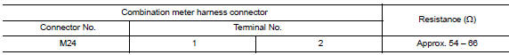
Is the measurement value within the specification? Yes >> go to 3.
No >> repair the combination meter branch line.
3.Check power supply and ground circuit
Check the power supply and the ground circuit of the combination meter. Refer to mwi-52, "combination meter : diagnosis procedure".
Is the inspection result normal? Yes (present error)>>replace the combination meter. Refer to mwi-77, "removal and installation".
Yes (past error)>>error was detected in the combination meter branch line.
No >> repair the power supply and the ground circuit.
 Eps branch line circuit
Diagnosis procedure
1.Check connector
Turn the ignition switch off.
Disconnect the battery cable from the negative terminal.
Check the terminals and connectors of the eps control unit for dam ...
 Strg branch line circuit
Diagnosis Procedure
1.Check connector
Turn the ignition switch off
Disconnect the battery cable from the negative terminal.
Check the terminals and connectors of the steering angle sensor for ...
Other materials:
Door handle
Front door handle
Front door handle : exploded view
Outside handle bracket
Front gasket
Outside handle
Intelligent key button
Door key cylinder rod
Inside handle assembly
Rear gasket
Front door handle : removal and installation - inside handle
REMOVAL
Remove front door ...
Making a call
To make a call, follow the procedure below:
Press the button on the
control panel.
The “Phone” screen will appear on the display.
Select one of the following options to make a
call:
“Phonebook”: Select the name from an entry
stored in the vehicle phonebook.
“Call ...
Fuses
Two types of fuses are used. Type A is used in
the fuse boxes in the engine compartment. Type
B is used in the passenger compartment fuse
box.
Type A fuses are provided as spare fuses. They
are stored in the passenger compartment fuse
box.
Type A fuses can be installed in the engine com ...
