Nissan Sentra Service Manual: Front wiper does not operate
Description
The front wiper does not operate under any operation conditions
Diagnosis procedure
Regarding wiring diagram information, refer to ww-24, "wiring diagram - with intelligent key" or ww-29, "wiring diagram - without intelligent key".
1. Check wiper relay operation
 Ipdm e/r auto active test
- Start IPDM E/R auto active test. Refer to WW-15, "Diagnosis Description" (with Intelligent Key system) or WW-19, "Diagnosis Description" (without Intelligent Key system).
- Check that the front wiper operates at the lo/hi operation.
 Consult active test
- Select FRONT WIPER of IPDM E/R active test item.
- While operating the test item, check that front wiper lo/hi operation and off.
Lo : front wiper lo operation
Hi : front wiper hi operation
Off : stop the front wiper.
Is the inspection result normal? Yes >> go to 5.
No >> go to 2.
2. Check front wiper motor fuse
- Turn the ignition switch OFF
- Check that the front wiper motor fuse 30a (no. 35, Located in the ipdm e/r) is not blown.
Is the fuse blown? Yes >> replace the fuse after repairing the affected circuit.
No >> go to 3.
3. Check front wiper motor (gnd) open circuit
- Disconnect front wiper motor.
- Check continuity between front wiper motor harness connector e1 and ground.
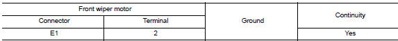
Is the inspection result normal? Yes >> go to 4.
No >> repair or replace the harness or connectors.
4. Check front wiper motor output voltage
 Consult active test
- Turn the ignition switch ON.
- Select FRONT WIPER of IPDM E/R active test item.
- With operating the test item, check voltage between ipdm e/r harness connector e45 and ground.
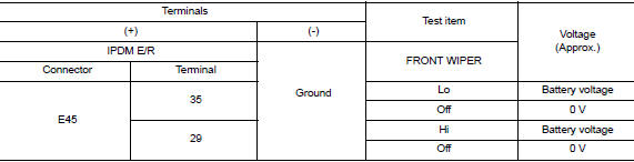
Is the inspection result normal? Yes lo circuit>>refer to ww-37, "diagnosis procedure".
Yes hi circuit>>refer to ww-39, "diagnosis procedure".
No >> replace ipdm e/r. Refer to pcs-30, "removal and installation" (with intelligent key system) or pcs-58, "removal and installation" (without intelligent key system).
5. Check front wiper request signal input
 Consult data monitor
- Select “fr wip req” of ipdm e/r data monitor item.
- Switch the front wiper switch to HI and LO.
- With operating the front wiper switch, check the monitor status.
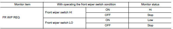
Is the inspection result normal? YES >> Replace IPDM E/R. Refer to PCS-30, "Removal and Installation" (with Intelligent Key system) or PCS-58, "Removal and Installation" (without Intelligent Key system).
NO >> GO TO 6.
6. Check combination switch (wiper and washer switch)
- Perform the inspection of the combination switch (wiper and washer switch). Refer to ww-8, "system description".
Is the inspection result normal? Yes >> replace bcm. Refer to bcs-73, "removal and installation" (with intelligent key system) or bcs- 126, "removal and installation" (without intelligent key system).
No >> repair or replace the malfunctioning parts.
 Wiper and washer system symptoms
Symptom table
Caution:
Perform the self-diagnosis with consult before performing the diagnosis
by symptom. Perform the
diagnosis by dtc if dtc is detected.
...
 Normal operating condition
Description
Front wiper motor protection function
Ipdm e/r may stop the front wiper to protect the front wiper motor if
any obstruction (operation resistance)
such as a large amount of snow ...
Other materials:
Condenser
Exploded view
Core support upper cover
High-pressure pipe
High-pressure flexible hose
Refrigerant pressure sensor
Condenser and liquid tank assembly
Core support upper
Front
Condenser
Condenser : removal and installation
REMOVAL
Discharge the refrigerant. Refer to HA-23, & ...
Dlc branch line circuit
Diagnosis procedure
1.Check connector
Turn the ignition switch off.
Disconnect the battery cable from the negative terminal
Check the terminals and connectors of the data link connector for damage,
bend and loose connection
(connector side and harness side).
Is the inspection result ...
Removal and installation
ACCELERATOR CONTROL SYSTEM
Exploded View
Accelerator pedal assembly
Brake pedal bracket
Locating hook
Locating pin
Removal and Installation
REMOVAL
Remove instrument lower panel LH. Refer to IP-21, "Removal and
Installation".
Disconnect the harness connector ...
