Nissan Sentra Service Manual: Instrument panel assembly
Exploded View
- Instrument panel assembly
- Ambient sensor
- Defroster grille (RH)
- Defroster grille (LH)
- Sunload sensor (if equipped)
- Side defroster grille (LH)
- Instrument side finisher (LH)
- Side ventilator grille (LH)
- Steering column upper cover
- Combination switch
- Steering column lower cover
- Instrument finisher (LH)
- Combination meter
- Switch carrier
- Instrument lower panel LH
- Cluster lid A
- Instrument finisher B
- Center ventilator grille assembly
- Cluster lid C
- Hazard switch
- AV control unit
- Cluster lid C lower
- A/C switch assembly
- Glove box lid
- Glove box mat
- Glove box assembly
- Side ventilator grille (RH)
- Instrument side finisher (RH)
- Side defroster grille (RH)
Removal and Installation
CAUTION:
- Be careful not to scratch instrument panel pad and other parts.
- Before servicing, turn ignition switch OFF, disconnect both battery terminals and wait at least three minutes.
REMOVAL
- Disconnect the negative and positive battery terminals, then wait at least three minutes. Refer to PG-50, "Removal and Installation (Battery)".
- Remove the instrument side finishers (1) (LH/RH) using a suitable tool.
NOTE:
LH side shown; RH side similar.
- Remove the front pillar finishers (LH/RH). Refer to INT-24, "FRONT PILLAR FINISHER : Removal and Installation".
- Remove the front kicking plates (LH/RH). Refer to INT-24, "KICKING PLATE INNER : Removal and Installation".
- Remove the instrument lower panel LH. Refer to IP-21, "Removal and Installation".
- Remove the audio unit. Refer to AV-58, "Removal and Installation" (BASE AUDIO), AV-122, "Removal and Installation" (DISPLAY AUDIO WITHOUT BOSE) or AV-203, "Removal and Installation" (DISPLAY AUDIO WITH BOSE).
- Remove the AV control unit. Refer to AV-298, "Removal and Installation" (NAVIGATION WITHOUT BOSE) or AV-406, "Removal and Installation" (NAVIGATION WITH BOSE).
- Remove the steering wheel. Refer to ST-10, "Removal and Installation".
- Remove the combination switch. Refer to BCS-75, "Removal and Installation".
- Remove the combination meter. Refer to MWI-77, "Removal and Installation".
- Remove the glove box assembly. Refer to IP-22, "Removal and Installation".
- Remove the center console assembly. Refer to IP-17, "Removal and Installation".
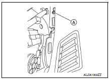
- Remove the instrument panel screws (A) (LH/RH).
NOTE:
The instrument panel screws (A) can be found near the side defroster grilles (LH/RH).
- Remove the remaining instrument panel screws.
- Disconnect the harness connector from the front passenger air bag module.
- Disconnect all remaining harness connectors.
- With the help of an assistant, remove the instrument panel assembly.
CAUTION:
Be careful not to scratch the instrument panel pad and other parts.
INSTALLATION
Installation is in the reverse order of removal.
- If replacing the instrument panel, transfer all the necessary parts to the new instrument panel.

 Steering column covers
Removal and Installation
REMOVAL
Remove the steering column cover screws (A), then remove the
steering column upper (1) and lower (2) covers.
NOTE:
Shown with steering wheel removed for ...
Other materials:
Preparation
Special service tools
The actual shape of the tools may differ from those illustrated here.
Commercial service tools
Clip list
Descriptions for Clips
Replace any clips which are damaged during removal or installation.
...
P1715 Input speed sensor
Description
ECM receives input speed sensor signal from TCM through CAN communication
line. ECM uses this signal for
engine control.
DTC Logic
DTC DETECTION LOGIC
NOTE:
If DTC P1715 is displayed with DTC UXXXX, first perform the trouble
diagnosis for DTC UXXXX.
If DTC P1715 is displa ...
Rear combination lamp
Exploded View
Rear combination lamp
Rear turn signal lamp bulb
Rear turn signal lamp socket
LED lamp harness connector
Rear combination lamp harness
connector
Back-up lamp bulb socket
Back-up lamp bulb
Disassembly and Assembly
DISASSEMBLY
WARNING:
Do not touch bulb whil ...
