Nissan Sentra Owners Manual: Instrument panel
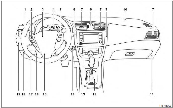
- Headlight/fog light (if so equipped)/turn signal switch
- Steering wheel switch for trip computer, audio control and Bluetooth® Hands-Free Phone System (if so equipped)
- DriverŌĆÖs supplemental air bag/Horn
- Meters and gauges
- Cruise control main/set switches (if so equipped)
- Windshield wiper/washer switch
- Ventilator
- Hazard warning flasher switch
- Audio system
- PassengerŌĆÖs supplemental air bag
- Glove box
- Shift lever
- Climate control
- Ignition switch (if so equipped)
- Telescopic steering
- Hood release
- Fuel filler door release
- ECO mode switch (P. 5-22); SPORT mode switch (P.5-22); Vehicle Dynamic Control (VDC) OFF switch
- Instrument brightness control. Power mirror switch. Trunk release
* Refer to the separate Navigation System OwnerŌĆÖs Manual (if so equipped).
See the page number indicated in parentheses for operating details.

 Meters and gauges
Engine coolant temperature gauge
Fuel gauge
Speedometer
Odometer/twin trip odometer/trip
computer/fuel economy/Eco Pedal Indicator
Tachometer
...
Other materials:
Component parts
Component Parts Location
Driver air bag module
Front passenger air bag off indicator
Front passenger air bag module
Front LH side air bag module
(RH similar)
LH side curtain air bag module
(view with headliner removed)
(RH similar)
Front LH seatbelt pre-tensioner
(view wit ...
DTC/circuit diagnosis
U1000 can comm
Description
Refer to LAN-7, "CAN COMMUNICATION SYSTEM : System Description".
Dtc logic
DTC DETECTION LOGIC
NOTE:
U1000 can be set if a module harness was disconnected and reconnected,
perhaps during a repair. Confirm
that there are actual CAN diagnostic symptoms a ...
Ecm branch line circuit
Diagnosis procedure
1.Check connector
Turn the ignition switch OFF.
Disconnect the battery cable from the negative terminal.
Check the terminals and connectors of the ECM for damage, bend and loose
connection (unit side and
connector side).
Is the inspection result normal?
Yes > ...
