Nissan Sentra Service Manual: DTC/circuit diagnosis
U1000 can comm
Description
Refer to LAN-7, "CAN COMMUNICATION SYSTEM : System Description".
Dtc logic
DTC DETECTION LOGIC
NOTE:
U1000 can be set if a module harness was disconnected and reconnected, perhaps during a repair. Confirm that there are actual CAN diagnostic symptoms and a present DTC by performing the Self Diagnostic Result procedure.
| CONSULT Display | DTC Detection Condition | Possible Cause |
| CAN COMM CIRCUIT [U1000] | When any listed module cannot communicate with CAN communication signal continuously for 2 seconds or more with ignition switch ON | In CAN communication system, any item (or
items) of the following listed below is malfunctioning.
|
Diagnosis procedure
1. PERFORM SELF DIAGNOSTIC RESULT
- Turn ignition switch ON and wait for 2 second or more.
- Check “SELF- DIAG RESULTS”.
Is “CAN COMM CIRCUIT” displayed? YES >> Perform CAN Diagnosis as described in DIAGNOSIS section of CONSULT operation manual.
NO >> Refer to GI-39, "Intermittent Incident".
U1010 control unit (can)
DTC Logic
DTC DETECTION LOGIC
| CONSULT Display | DTC Detection Condition | Possible Cause |
| CONTROL UNIT (CAN) [U1010] | BCM detected internal CAN communication circuit malfunction. | BCM |
Diagnosis Procedure
1.REPLACE BCM
When DTC “U1010” is detected, replace BCM.
>> Replace BCM. Refer to BCS-126, "Removal and Installation".
Power supply and ground circuit
Diagnosis procedure
Regarding Wiring Diagram information, refer to BCS-111, "Wiring Diagram".
1.CHECK FUSES AND FUSIBLE LINK
Check that the following fuses and fusible link are not blown.
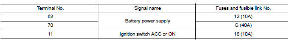
Is the fuse blown? YES >> Replace the blown fuse or fusible link after repairing the affected circuit.
NO >> GO TO 2.
2.Check power supply circuit
- Turn ignition switch OFF.
- Disconnect BCM connectors.
- Check voltage between BCM connector and ground.
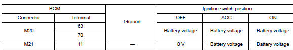
Is the inspection result normal? YES >> GO TO 3.
NO >> Repair harness or connector.
3.Check ground circuit
Check continuity between bcm connector and ground.
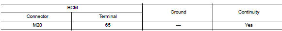
Is the inspection result normal? Yes >> inspection end.
No >> repair harness or connector.
Door switch
Description
Detects door open/close condition.
Component function check
1.Check function
 With consult
Check door switches DOOR SW-DR, DOOR SW-AS, DOOR SW-RL, DOOR SW-RR in Data Monitor mode with CONSULT.
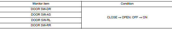
Is the inspection result normal? Yes >> door switch is ok.
No >> refer to dlk-253, "diagnosis procedure".
Diagnosis procedure
Regarding wiring diagram information, refer to dlk-224, "wiring diagram".
1.Check door switch input signal
- Turn ignition switch OFF.
- Check signal between BCM connector and ground with oscilloscope.
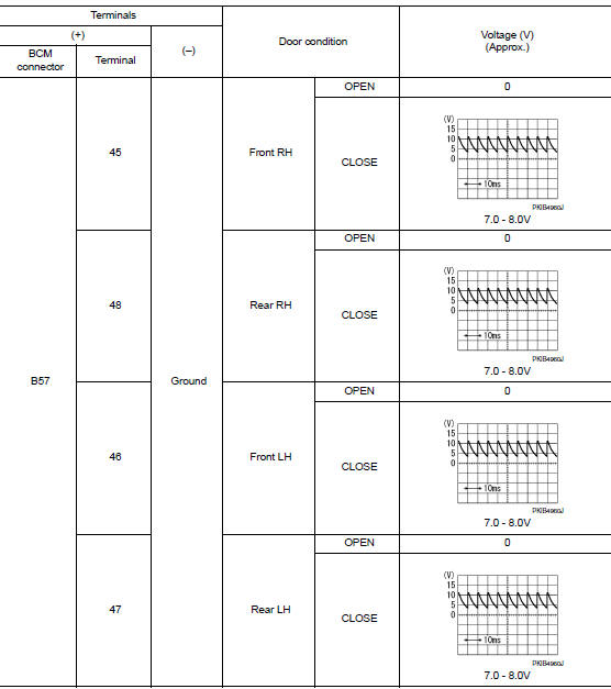
Is the inspection result normal? Yes >> go to 4
No >> go to 2
2.Check door switch circuit
- Disconnect bcm connector.
- Check continuity between BCM connector and door switch connector.
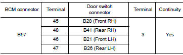
- Check continuity between bcm connector and ground.
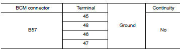
Is the inspection result normal? YES >> GO TO 3 NO >> Repair or replace harness between BCM and door switch.
3.Check door switch
Refer to DLK-255, "Component Inspection".
Is the inspection result normal? YES >> GO TO 4 NO >> Replace malfunctioning door switch.
4.Check intermittent incident
Refer to gi-39, "intermittent incident".
>> Inspection end.
Component inspection
1.Check door switch
- Turn ignition switch off.
- Disconnect door switch connector.
- Check door switch.
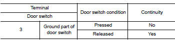
Is the inspection result normal? Yes >> inspection end.
No >> replace malfunctioning door switch.
Door lock and unlock switch
Driver side
Driver side : description
Transmits door lock/unlock operation to bcm.
Driver side : component function check
1.Check function
 With consult
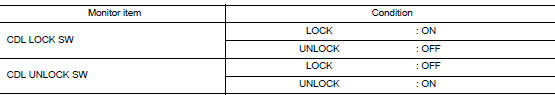
Check CDL LOCK SW, CDL UNLOCK SW in Data Monitor mode with CONSULT.
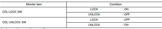
Is the inspection result normal? Yes >> door lock and unlock switch is ok.
No >> refer to dlk-256, "driver side : diagnosis procedure".
Driver side : diagnosis procedure
Regarding Wiring Diagram information, refer to DLK-233, "Wiring Diagram".
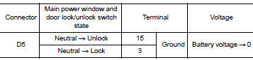
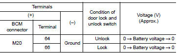
1.Check power window switch output signal
- Turn ignition switch on.
- Check voltage at the main power window and door lock/unlock switch connector when the switch (driver side) is turned to “LOCK” or “UNLOCK”.
Is the inspection result normal? Yes >> go to 5
No >> go to 2
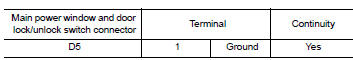
2.Check power window switch ground
- Turn ignition switch off
- Disconnect main power window and door lock/unlock switch connector.
- Check continuity between main power window and door lock/unlock switch connector and ground.
Is the inspection result normal? Yes >> go to 3
No >> repair or replace harness.
3.Check power window switch
Check continuity between main power window and door lock/unlock switch terminals.
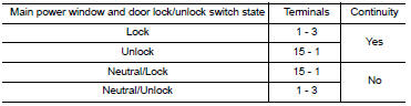
Is the inspection result normal? Yes >> go to 4 no >> replace main power window and door lock/unlock switch. Refer to pwc-70, "removal and installation".
4.Check power window switch circuits
- Disconnect BCM connector.
- Check continuity between bcm connector and main power window and door lock/unlock switch connector.
- Check continuity between bcm connector and ground.
Is the inspection result normal? Yes >> go to 5
NO >> Repair or replace harness.
5.Check intermittent incident
Refer to gi-39, "intermittent incident".
>> Inspection end.
Passenger side
PASSENGER SIDE : Description
Transmits door lock/unlock operation to bcm.
PASSENGER SIDE : Component Function Check
1.Check function
 With consult
Check cdl lock sw, cdl unlock sw in data monitor mode with consult.
Is the inspection result normal? Yes >> door lock and unlock switch is ok.
No >> refer to dlk-258, "passenger side : diagnosis procedure".
PASSENGER SIDE : Diagnosis Procedure
Regarding wiring diagram information, refer to dlk-233, "wiring diagram".
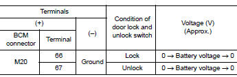
1.Check power window switch output signal
- Turn ignition switch ON.
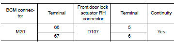
- Check voltage at the power window and door lock/unlock switch rh connector when the switch (passenger side) is turned to “lock” or “unlock”.
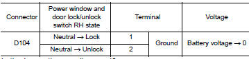
Is the inspection result normal? YES >> GO TO 5
No >> go to 2
2.Check power window switch ground
- Turn ignition switch off.
- Disconnect power window and door lock/unlock switch RH connector.
- Check continuity between power window and door lock/unlock switch RH connector and ground.
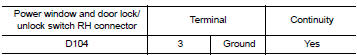
Is the inspection result normal? Yes >> go to 3
NO >> Repair or replace harness.
3.Check power window switch
Check continuity between power window and door lock/unlock switch rh terminals.
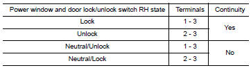
Is the inspection result normal? YES >> GO TO 4
No >> replace power window and door lock/unlock switch rh.
4.Check power window switch circuits
- Disconnect bcm connector
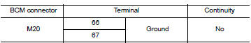
- Check continuity between bcm connector and power window and door lock/unlock switch rh connector.
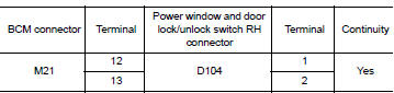
- Check continuity between BCM connector and ground.
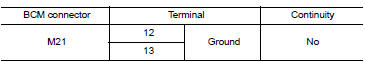
Is the inspection result normal? YES >> GO TO 5
No >> repair or replace harness.
5.Check intermittent incident
Refer to gi-39, "intermittent incident".
>> Inspection end.
Key cylinder switch
Description
When the mechanical key is inserted and turned into the front door lock key cylinder switch LH, the switch transmits the LOCK or UNLOCK signal directly to the BCM.
Component function check
1.Check door key cylinder switch input signal
Check KEY CYL UN-SW, KEY CYL UN-SW in “DATA MONITOR” mode for “POWER DOOR LOCK SYSTEM” with CONSULT. Refer to DLK-221, "DOOR LOCK : CONSULT Function (BCM - DOOR LOCK)".
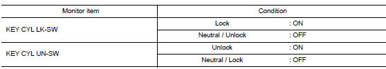
Is the inspection result normal? YES >> Key cylinder switch is OK.
NO >> Refer to DLK-260, "Diagnosis Procedure".
Diagnosis procedure
Regarding wiring diagram information, refer to dlk-233, "wiring diagram".
1.Check door key cylinder switch input signal
- Turn ignition switch on.
- Check voltage between bcm connector and ground.
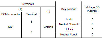
Is the inspection result normal? Yes >> front door lock key cylinder switch lh is ok.
No >> go to 2
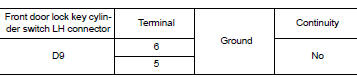
2.Check door key cylinder switch ground circuit
- Turn ignition switch OFF.
- Disconnect front door lock key cylinder switch lh connector.
- Check continuity between front door lock key cylinder switch lh connector and ground.
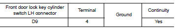
Is the inspection result normal?
YES >> GO TO 3
No >> repair or replace harness.
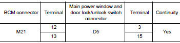
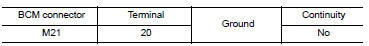
3.Check door key cylinder signal circuit
- Disconnect bcm connector m21.
- Check continuity between front door lock key cylinder switch LH connector and BCM connector M21.
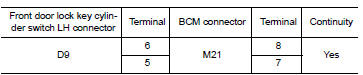
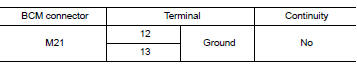
- Check continuity between front door lock key cylinder switch LH connector and ground.
Is the inspection result normal? Yes >> go to 4
No >> repair or replace harness.
4.Check door key cylinder switch
Check door key cylinder switch.
Refer to dlk-261, "component inspection".
Is the inspection result normal? Yes >> check intermittent incident. Refer to gi-39, "intermittent incident".
No >> replace front door lock key cylinder switch lh.
Component inspection
1.Check door key cylinder switch
Check front door lock key cylinder switch lh.
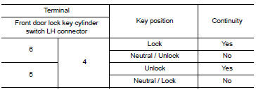
Is the inspection result normal? Yes >> key cylinder switch is ok.
No >> replace front door lock key cylinder switch lh.
KEY SWITCH (BCM INPUT)
Diagnosis Procedure
Regarding wiring diagram information, refer to dlk-224, "wiring diagram".
1.Check key switch input signal
 With consult
Check key switch "key on sw" in data monitor mode with consult. Refer to dlk-221, "door lock : consult function (bcm - door lock)".
- When key is inserted to ignition key cylinder:
Key on sw : on
- When key is removed from ignition key cylinder:
Key on sw : off
 Without consult
Check voltage between bcm connector m21 terminal 37 and ground.
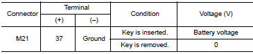
Is the inspection result normal? Yes >> key switch (insert) circuit is ok.
No >> go to 2
2.Check key switch (insert)
- Turn ignition switch off.
- Disconnect key switch connector.
- Check continuity between key switch terminals.
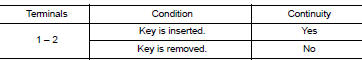
Is the inspection result normal? YES >> Repair or replace harness or fuse.
NO >> Replace key switch.
Door lock actuator
DRIVER SIDE
DRIVER SIDE : Description
Locks/unlocks the door with the signal from bcm.
DRIVER SIDE : Component Function Check
1.Check function
- Use consult to perform active test (“door lock”).
- Touch “all lock” or “all unlock” to check that it works normally.
Is the inspection result normal? Yes >> door lock actuator is ok.
No >> refer to dlk-263, "driver side : diagnosis procedure".
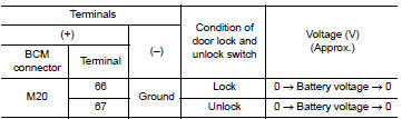
DRIVER SIDE : Diagnosis Procedure
Regarding wiring diagram information, refer to dlk-233, "wiring diagram".
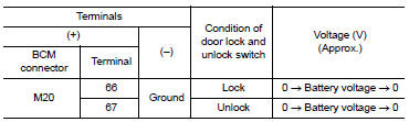
1.Check output signal
Check voltage between bcm connector and ground.
Is the inspection result normal? Yes >> go to 3
No >> go to 2
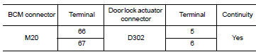
2.Check door lock actuator circuit
- Turn ignition switch off.
- Disconnect bcm and front door lock actuator driver side connector.
- Check continuity between bcm connector and front door lock actuator driver side connector.
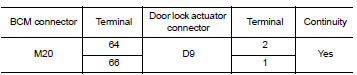
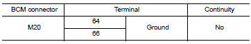
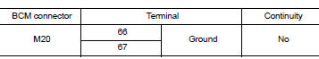
- Check continuity between bcm connector and ground.
Is the inspection result normal? Yes >> replace front door lock actuator lh.
No >> repair or replace harness.
3.Check intermittent incident
Refer to gi-39, "intermittent incident".
>> Inspection end.
Passenger side
PASSENGER SIDE : Description
Locks/unlocks the door with the signal from bcm.
PASSENGER SIDE :Component Function Check
1.Check function
- Use consult to perform active test (“door lock”).
- Touch “all lock” or “all unlock” to check that it works normally.
Is the inspection result normal? Yes >> door lock actuator is ok.
No >> refer to dlk-264, "passenger side : diagnosis procedure".
PASSENGER SIDE : Diagnosis Procedure
Regarding wiring diagram information, refer to dlk-233, "wiring diagram".
1.Check door lock actuator signal
Check voltage between bcm connector and ground.
Is the inspection result normal? Yes >> go to 3
No >> go to 2
2.Check door lock actuator circuit
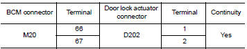
- Disconnect bcm and front door lock actuator rh connectors.
- Check continuity between bcm connector and front door lock actuator rh.
- Check continuity between bcm connector and ground.
Is the inspection result normal? Yes >> replace front door lock actuator rh.
No >> repair or replace harness.
3.Check intermittent incident
Refer to gi-39, "intermittent incident".
>> Inspection end.
Rear lH
Rear lh : description
Locks/unlocks the door with the signal from bcm.
Rear lh : component function check
1.Check function
- Use consult to perform active test (“door lock”).
- Touch “all lock” or “all unlock” to check that it works normally.
Is the inspection result normal? Yes >> door lock actuator is ok.
No >> refer to dlk-265, "rear lh : diagnosis procedure".
Rear lH : diagnosis procedure
Regarding Wiring Diagram information, refer to DLK-233, "Wiring Diagram".
1.Check door lock actuator signal
Check voltage between bcm connector and ground.
Is the inspection result normal? Yes >> go to 3
No >> go to 2
2.Check door lock actuator circuit
- Disconnect bcm and rear door lock actuator lh connectors.
- Check continuity between bcm connector and rear door lock actuator lh connectors.
- Check continuity between BCM connector and ground.

Is the inspection result normal? Yes >> replace rear door lock actuator lh.
No >> repair or replace harness.
3.Check intermittent incident
Refer to gi-39, "intermittent incident".
>> Inspection end.
Rear RH
REAR RH : Description
Locks/unlocks the door with the signal from bcm.
REAR RH : Component Function Check
1.Check function
- Use consult to perform active test (“door lock”).
- Touch “ALL LOCK” or “ALL UNLOCK” to check that it works normally.
Is the inspection result normal? Yes >> door lock actuator is ok.
No >> refer to dlk-266, "rear rh : diagnosis procedure".
REAR RH : Diagnosis Procedure
Regarding Wiring Diagram information, refer to DLK-233, "Wiring Diagram".
1.Check door lock actuator signal
Check voltage between bcm connector and ground.
Is the inspection result normal? Yes >> go to 3
NO >> GO TO 2
2.Check door lock actuator circuit
- Disconnect bcm and rear door lock actuator rh connectors.
- Check continuity between bcm connector and rear door lock actuator rh connectors.
- Check continuity between bcm connector and ground.
Is the inspection result normal? Yes >> replace rear door lock actuator rh.
No >> repair or replace harness.
3.Check intermittent incident
Refer to gi-39, "intermittent incident".
>> Inspection end.
Remote keyless entry receiver
Description
Receives keyfob operation and transmits to bcm.
Component Function Check
1.CHECK FUNCTION
 With consult
Check remote keyless entry receiver keyless lock, keyless unlock, and keyless panic in data monitor mode with consult.
Is the inspection result normal? Yes >> remote keyless entry receiver is ok.
No >> refer to dlk-268, "diagnosis procedure".
Diagnosis Procedure
Regarding wiring diagram information, refer to dlk-224, "wiring diagram".
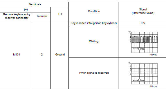
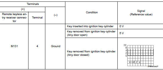
1.Check remote keyless entry receiver output signal
- Turn ignition switch off.
- Check signal between remote keyless entry receiver connector and ground with oscilloscope.
Is the inspection result normal? Yes >> go to 7
No >> go to 2
2.Check remote keyless entry receiver power supply
- Disconnect remote keyless entry receiver connector.
- Check signal between remote keyless entry receiver connector and ground with oscilloscope.
Is the inspection result normal? Yes >> go to 4
No >> go to 3
3.Check remote keyless entry receiver circuit 1
- Disconnect BCM connector.
- Check continuity between BCM connector and remote keyless entry receiver connector.
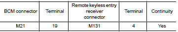
- Check continuity between bcm connector and ground.
Is the inspection result normal? Yes >> reconnect bcm, go to 4
No >> repair or replace harness between bcm and remote keyless entry receiver.
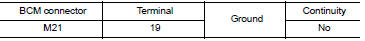
4.Check remote keyless entry receiver ground circuit
Check continuity between remote keyless entry receiver connector and ground.
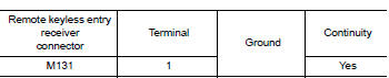
Is the inspection result normal? Yes >> go to 6
NO >> GO TO 5
5.Check remote keyless entry receiver circuit 2
Check continuity between bcm connector and remote keyless entry receiver connector.
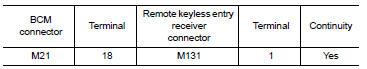
Is the inspection result normal? Yes >> go to 7
No >> repair or replace harness between bcm and remote keyless entry receiver.
6.Check remote keyless entry receiver circuit 3
Check continuity between bcm connector and remote keyless entry receiver connector.
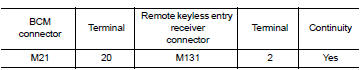
- Check continuity between bcm connector and ground.
Is the inspection result normal? Yes >> go to 7
No >> repair or replace harness between bcm and remote keyless entry.
7.Check intermittent incident
Refer to GI-39, "Intermittent Incident".
>> Inspection End.
Keyfob battery and function
Description
The following functions are available when having and carrying the keyfob.
- Door lock/unlock
- Panic mode (horn and headlamp operation)
Remote control entry function and panic alarm function are available when operating the remote buttons.
Component Function Check
Note:
The Signal Tech II Tool (J-50190) can be used to perform the following functions. Refer to the Signal Tech II User Guide for additional information.
- Check keyfob relative signal strength
- Confirm vehicle antenna signal strength
1.Check function
 With consult
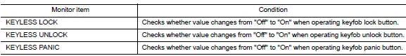
Check remote keyless entry receiver keyless lock, keyless unlock, and keyless panic in data monitor mode with consult.
| Monitor item | Condition |
| Keyless lock | Checks whether value changes from "Off" to "On" when operating keyfob lock button. |
| KEYLESS UNLOCK | Checks whether value changes from "off" to "on" when operating keyfob unlock button. |
| Keyless panic | Checks whether value changes from "off" to "on" when operating keyfob panic button. |
Is the inspection result normal? Yes >> keyfob is ok.
No >> refer to dlk-271, "diagnosis procedure".
Diagnosis Procedure
Note:
The signal tech ii tool (j-50190) can be used to perform the following functions. Refer to the signal tech ii user guide for additional information.
- Check keyfob relative signal strength
- Confirm vehicle antenna signal strength
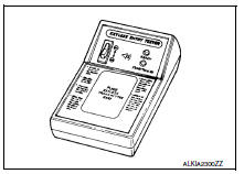
1.Check keyfob function
Check keyfob function using signal tech ii tool j-50190 or remote keyless entry tester j-43241 (shown).
Does the test pass? Yes >> keyfob is ok.
No >> go to 2
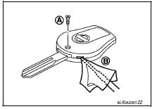
2. Check keyfob components
- Remove the screw (a).
- Insert a small screwdriver into the slit of the corner (b) and twist it to separate the upper part from the power part. Use a cloth to protect the casing.
Caution:
- Do not touch the circuit board or battery terminal.
- The keyfob is water-resistant. However, if it does get wet, immediately wipe it dry.
- Remove the keyfob battery.
Caution:
Keep dirt, grease, and other foreign materials off the electrode contact area.
- Visually inspect keyfob internal components.
Is the inspection result normal? Yes >> go to 3
NO >> Repair or replace malfunctioning parts.
3.Check keyfob battery
Check by connecting a resistance (approximately 300ù) so that the current value becomes about 10 ma.
Standard : approx. 2.5 - 3.0V
Is the measurement value within specification? Yes >> keyfob battery is ok. Check remote keyless entry receiver. Refer to dlk-268, "component function check".
No >> go to 4
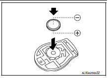
4. Replace keyfob battery
- Replace the keyfob battery with a new one (CR1620 or equivalent).
Caution:
- When replacing battery, keep dirt, grease, and other foreign materials off the electrode contact area.
- Make sure that the + side faces the bottom of the case.
- Align the tips of the upper and lower parts, and then push them together until it is securely closed.
- After replacing the battery, check that all keyfob functions work properly.
Is the inspection result normal? Yes >> keyfob is ok.
No >> check remote keyless entry receiver. Refer to dlk-268, "component function check".
Horn function
Description
Perform answer-back for each operation with horn.
Component function check
1.Check function
- Select horn in “active test” mode with consult.
- Check the horn operation.

Is the operation normal? Yes >> inspection end.
No >> refer to dlk-273, "diagnosis procedure".
Diagnosis procedure
Regarding wiring diagram information, refer to dlk-224, "wiring diagram".
1.Check horn function
Check horn function with horn switch.
Does the horn sound? YES >> GO TO 2
No >> refer to hrn-3, "wiring diagram".
2.Check horn relay power supply
- Turn ignition switch on.
- Perform “active test” (“horn”) with consult
- Using an oscilloscope or analog voltmeter to check voltage between ipdm e/r connector and ground.
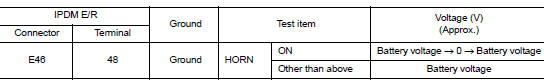
Is the inspection result normal? Yes >> repair or replace open harness between ipdm e/r and horn relay.
No >> go to 3
3.Check horn relay circuit
Turn ignition switch off.
Disconnect IPDM E/R and horn relay connector.
Check continuity between ipdm e/r harness connector and horn relay harness connector.
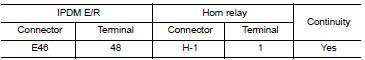
- Check continuity between ipdm e/r harness connector and ground.
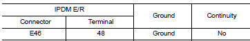
Is the inspection result normal? Yes >> go to 4
NO >> Repair or replace harness.
4.Check intermittent incident
Refer to gi-39, "intermittent incident".
Is the inspection result normal? Yes >> replace ipdm e/r. Refer to pcs-58, "removal and installation".
No >> repair or replace the malfunctioning part.
Trunk lid opener actuator
Component function check
1.Check function
- Select intelligent key of bcm using consult
- Select trunk/glass hatch in active test mode.
- Touch open to check that it works normally.
Is the inspection result normal? Yes >> trunk lid opener actuator is ok.
No >> refer to dlk-275, "diagnosis procedure".
Diagnosis procedure
Regarding wiring diagram information, refer to dlk-241, "wiring diagram".
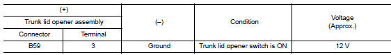
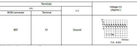
1.Check trunk lid opener input signal
- Turn ignition switch off
- Disconnect trunk lid opener assembly connector.
- Check voltage between trunk lid opener assembly harness connector and ground.
Is the inspection result normal? YES >> GO TO 3.
NO >> GO TO 2.
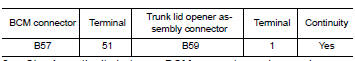
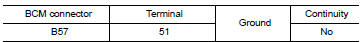
2.Check trunk lid opener actuator circuit
- Disconnect BCM connector
- Check continuity between BCM harness connector and trunk lid opener assembly harness connector.
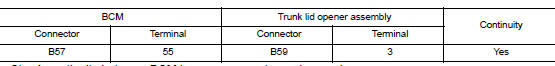
- Check continuity between bcm harness connector and ground.
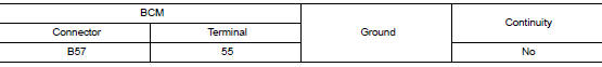
Is the inspection result normal? Yes >> replace bcm. Refer to bcs-126, "removal and installation".
No >> repair or replace harness.
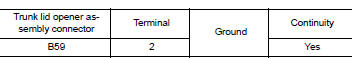
3.Check trunk lid opener actuator ground circuit
Check continuity between trunk lid opener assembly harness connector and ground.
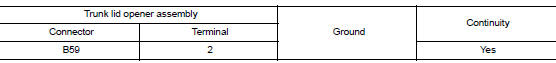
Is the inspection normal? YES >> Replace trunk lid opener assembly.
NO >> Repair or replace harness.
Trunk lid opener switch
Component Function Check
1.Check function
- Select trunk of bcm using consult.
- Select tr/bd open sw in data monitor mode.
- Check that the function operates normally according to the following conditions.
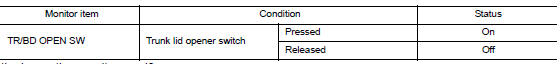
Is the inspection result normal? YES >> Trunk lid opener switch is OK.
NO >> Refer to DLK-277, "Diagnosis Procedure".
Diagnosis Procedure
Regarding wiring diagram information, refer to dlk-241, "wiring diagram".
1.Check trunk lid opener input signal
- Turn ignition switch off.
- Disconnect trunk lid opener switch connector.
- Check signal between trunk lid opener switch harness connector and ground using oscilloscope.
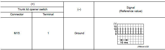
Is the inspection result normal? YES >> GO TO 3.
NO >> GO TO 2.
2.Check trunk lid opener switch circuit
- Disconnect bcm connector.
- Check continuity between BCM harness connector and trunk lid opener switch harness connector.
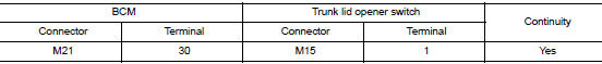
- Check continuity between bcm harness connector and ground.
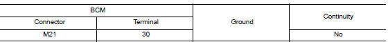
Is the inspection result normal? YES >> Replace BCM. Refer to BCS-126, "Removal and Installation".
NO >> Repair or replace harness.
3.Check trunk lid opener switch ground circuit
Check continuity between trunk lid opener switch harness connector and ground.
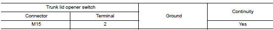
Is the inspection result normal? YES >> GO TO 4.
NO >> Repair or replace harness.
4.Check trunk lid opener switch
Refer to dlk-277, "component function check".
Is the inspection result normal? Yes >> go to 5.
No >> replace trunk lid opener switch.
5.Check intermittent incident
Refer to gi-39, "intermittent incident".
>> Inspection end.
Component Inspection
1.Check trunk lid opener switch
- Turn ignition switch off.
- Disconnect trunk lid opener switch connector
- Check continuity between trunk lid opener switch terminals.
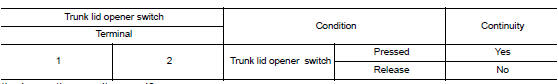
Is the inspection result normal? YES >> Inspection End.
NO >> Replace trunk lid opener switch.
Trunk lamp switch
Description
Detects trunk open/close condition.
Component function check
1.Check function
 With consult
Check trnk/hat mntr in data monitor mode with consult.
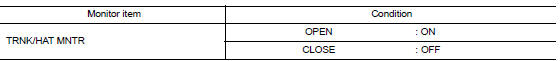
Is the inspection result normal? Yes >> trunk room lamp switch is ok.
No >> refer to dlk-279, "diagnosis procedure".
Diagnosis procedure
Regarding wiring diagram information, refer to dlk-241, "wiring diagram".
1.Check trunk room lamp switch input signal
- Turn ignition switch off.
- Check voltage between bcm connector and ground.
Is the inspection result normal? Yes >> go to 6
No >> go to 2
2.Check trunk room lamp switch circuit
- Disconnect bcm and trunk lid opener assembly connector.
- Check continuity between bcm connector and trunk lid opener assembly connector.
- Check continuity between BCM connector and ground.
Is the inspection result normal? Yes >> go to 3
No >> repair or replace harness between bcm and trunk lid opener assembly.
3.Check trunk room lamp switch ground circuit
Check continuity between trunk lid opener assembly connector and ground.
Is the inspection result normal? YES >> GO TO 4
No >> repair or replace trunk lid opener assembly ground circuit.
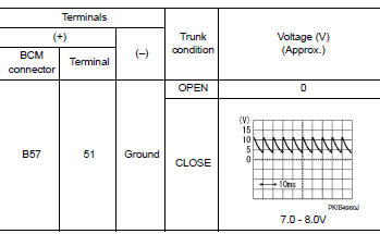
4.Check bcm output signal
- Ensure trunk lid remains closed during this step.
- Connect bcm connector.
- Check voltage between BCM connector and ground.
Is the inspection result normal? Yes >> go to 5
No >> replace bcm. Refer to bcs-126, "removal and installation".
5.Check trunk room lamp switch
Refer to dlk-277, "component function check".
Is the inspection result normal? Yes >> go to 6
No >> replace trunk lid opener assembly.
6.Check intermittent incident
Refer to gi-39, "intermittent incident".
>> Inspection end.
Component inspection
1.Check trunk room lamp switch
- Turn ignition switch off.
- Disconnect trunk lid opener assembly connector.
- Check trunk room lamp switch.
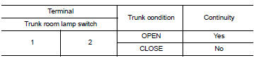
Is the inspection result normal? YES >> Inspection End.
NO >> Replace trunk lid opener assembly.
Warning chime function
Description
Performs operation method guide and warning with buzzer.
Component function check
1.Check function
 With consult
- Check the operation with “BUZZER” in the Active Test.
- Touch “ign key warn alm”, “seat belt warn test”or “light warn alm”on screen.
Is the inspection result normal? Yes >> warning buzzer into combination meter is ok.
No >> refer to dlk-282, "diagnosis procedure".
Diagnosis procedure
1.Check meter buzzer circuit
Operate the hazard lights by turning on the hazard warning switch.
Is the inspection result normal? Yes >> go to 2
No >> replace combination meter. Refer to mwi-77, "removal and installation".
2.Check intermittent incident
Refer to gi-39, "intermittent incident".
>> Inspection end.
Hazard function
Description
Perform answer-back for each operation with number of blinks.
Component function check
1.Check function
Check hazard warning lamp (“flasher”) in active test.
Is the inspection result normal? Yes >> hazard warning lamp circuit is ok.
No >> refer to dlk-283, "diagnosis procedure".
Diagnosis procedure
1.Check hazard switch circuit
Operate the hazard lights by turning on the hazard warning switch.
Is the inspection result normal? Yes >> go to 2
NO >> Repair or replace hazard warning switch circuit. Refer to EXL-129, "Removal and Installation".
2.Check intermittent incident
Refer to gi-39, "intermittent incident".
>> Inspection end.
Keyfob id set up with consult
ID Code Entry Procedure
Keyfob id set up with consult
Note:
- If a keyfob is lost, the id code of the lost keyfob must be erased to prevent unauthorized use. A specific id code can be erased with consult. However, when the id code of a lost keyfob is not known, all controller id codes should be erased. After all id codes are erased, the id codes of all remaining and/or new keyfobs must be re-registered.
- When registering an additional keyfob, the existing id codes in memory may or may not be erased. If five id codes are stored in memory when an additional code is registered, only the oldest code is erased. If less than five codes are stored in memory when an additional code is registered, the new id code is added and no id codes are erased.
- Entry of a maximum of five id codes is allowed. When more than five codes are entered, the oldest id code will be erased
- Even if the same id code that is already in memory is input, the same id code can be entered. The code is counted as an additional code.
- Turn ignition switch on.
- Select bcm.
- Select multi remote ent.
- Select work support.
- You can register, erase or confirm a keyfob ID code. To register a new code, select the following option and follow CONSULT instructions:
- Remo cont id regist
Use this mode to register a keyfob id code.
Note:
Register the id code when keyfob or bcm is replaced, or when additional keyfob is required.
- REMO CONT ID ERASUR
Use this mode to erase a keyfob id code.
- Remo cont id confir
Use this mode to confirm if a keyfob id code is registered or not.
Keyfob id set up without consult
Id code entry procedure
Keyfob id set up without consult
Note:
- If a keyfob is lost, the ID code of the lost keyfob must be erased to
prevent unauthorized use. A specific ID
code can be erased with CONSULT. However, when the ID code of a lost keyfob
is not known, all controller Id codes should be erased. After all id codes
are erased, the id codes of all remaining and/or new keyfobs
must be re-registered.
To erase all id codes in memory, register one id code (keyfob) five times. After all id codes are erased, the id codes of all remaining and/or new keyfobs must be re-registered.
- When registering an additional keyfob, the existing id codes in memory may or may not be erased. If five id codes are stored in memory, when an additional code is registered, only the oldest code is erased. If less than five id codes are stored in memory, when an additional id code is registered, the new id code is added and no id codes are erased.
- If you need to activate more than two additional new keyfobs, repeat the procedure “additional id code entry” for each new keyfob dlk-284, "id code entry procedure" (with consult), dlk-285, "id code entry procedure" (without consult).
- A maximum amount of five id codes is allowed. When more than five id codes are entered, the oldest id code will be erased.
- Even if same id code that is already in the memory is input, the same id code can be entered. The code is counted as an additional code.
 Basic inspection
Diagnosis and repair work flow
Work Flow
OVERALL SEQUENCE
DETAILED FLOW
1.GET INFORMATION FOR SYMPTOM
Get detailed information from the customer about the symptom (the
condition and the ...
 Symptom diagnosis
Power door lock system symptoms
Symptom table
Door lock/unlock function malfunction
Note:
Before performing the diagnosis in the following table, check “WORK
FLOW”. Refer to DLK-24 ...
Other materials:
Precaution for supplemental restraint system (srs) "air bag" and "seat belt
pre-tensioner"
The Supplemental Restraint System such as “AIR BAG” and “SEAT BELT PRE-TENSIONER”,
used along
with a front seat belt, helps to reduce the risk or severity of injury to the
driver and front passenger for certain
types of collision. Information necessary to service the system ...
Combination switch
Exploded view
Combination switch
Combination switch harness connector
Front
NOTE:
Shown with the steering wheel removed for clarity only.
Removal and installation
REMOVAL
CAUTION:
Before servicing, turn the ignition switch OFF, disconnect both
battery terminals and wait at l ...
Control Units and Electrical Parts
PRECAUTIONS
Never reverse polarity of battery terminals.
Install only parts specified for a vehicle.
Before replacing the control unit, check the input and output and
functions of the component parts.
Do not apply excessive force when disconnecting a connector.
Do not apply exce ...
