Nissan Sentra Service Manual: Illumination control switch signal circuit
Diagnosis procedure
Regarding wiring diagram information, refer to mwi-28, "wiring diagram".
1.Check combination meter input signal
- Turn ignition switch on.
- Check voltage between the following terminals of the illumination control switch.
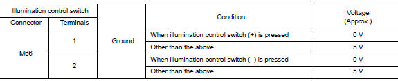
Is the inspection result normal? YES >> Inspection End.
NO >> GO TO 2.
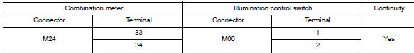
2.Check illumination control switch signal circuit
- Turn ignition switch off
- Disconnect combination meter connector m24 and illumination control switch connector m66.
- Check continuity between combination meter harness connector and illumination control switch harness connector.
- Check continuity between combination meter harness connector and ground.
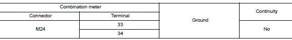
Is the inspection result normal? Yes >> check illumination control switch. Refer to mwi-56, "component inspection".
No >> repair or replace harness or connector.
Component inspection
1.Check illumination control switch
- Turn ignition switch OFF.
- Disconnect illumination control switch connector.
- Check illumination control switch.
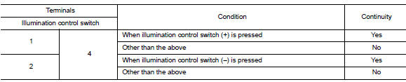
Is the inspection result normal? Yes >> inspection end.
No >> replace illumination control switch. Refer to mwi-80, "removal and installation".
 Steering switch (meter control switch) signal circuit
Diagnosis Procedure
Regarding wiring diagram information, refer to mwi-28, "wiring diagram".
1.Check combination meter input signal
Turn ignition switch on.
Measure voltage between ...
 Fuel level sensor signal circuit
Description
The fuel level sensor unit and fuel pump detects the approximate fuel level
in the fuel tank and transmits the
fuel level signal to the combination meter.
Component function check
1 ...
Other materials:
Precaution for Work
When removing or disassembling each component, be careful not to damage
or deform it. If a component
may be subject to interference, be sure to protect it with a shop cloth.
When removing (disengaging) components with a screwdriver or similar
tool, be sure to wrap the component
with a ...
Wiring diagram
Display audio without bose
Wiring diagram
...
DTC/circuit diagnosis
U1000 CAN COMM CIRCUIT
Description
Refer to lan-7, "can communication system : system description".
Dtc logic
Dtc detection logic
Note:
U1000 can be set if a module harness was disconnected and reconnected,
perhaps during a repair. Confirm
that there are actual CAN diagnostic symp ...
