Nissan Sentra Owners Manual: Head restraints/Headrests
| WARNING Head restraints/headrests supplement the other vehicle safety systems. They may provide additional protection against injury in certain rear end collisions. Adjustable head restraints/headrests must be adjusted properly, as specified in this section. Check the adjustment after someone else uses the seat. Do not attach anything to the head restraint/headrest stalks or remove the head restraint/headrest. Do not use the seat if the head restraint/headrest has been removed. If the head restraint/headrest was removed, reinstall and properly adjust the head restraint/headrest before an occupant uses the seating position. Failure to follow these instructions can reduce the effectiveness of the head restraints/headrests. This may increase the risk of serious injury or death in a collision. |
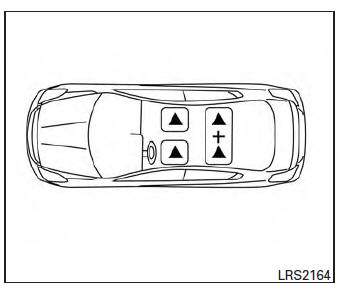
The illustration shows the seating positions equipped with head restraints/headrests.
▲ Indicates the seating position is equipped with a head restraint.
■ Indicates the seating position is equipped with a headrest.
+ Indicates the seating position is not equipped with a head restraint or headrest (if applicable).
- Your vehicle is equipped with a head restraint/headrest that may be integrated, adjustable or non-adjustable.
- Adjustable head restraints/headrests have multiple notches along the stalks to lock them in a desired adjustment position.
- The non-adjustable head restraints/ headrests have a single locking notch to secure them to the seat frame.
- Proper Adjustment:
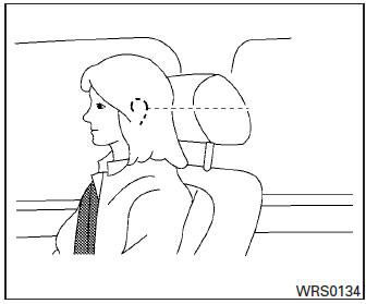
- For the adjustable type, align the head restraint/headrest so the center of your ear is approximately level with the center of the head restraint/headrest.
- If your ear position is still higher than the recommended alignment, place the head restraint/headrest at the highest position.
- If the head restraint/headrest has been removed, ensure that it is reinstalled and locked in place before riding in that designated seating position.
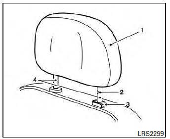
Adjustable head restraint/headrest components
- Removable head restraint/headrest
- Multiple notches
- Lock knob
- Stalks
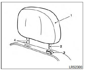
Non-adjustable head restraint/ headrest components
- Removable head restraint/headrest
- Single Notch
- Lock knob
- Stalks
Remove
Use the following procedure to remove the head restraint/headrest.
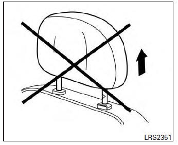
- Pull the head restraint/headrest up to the highest position.
- Push and hold the lock knob.
- Remove the head restraint/headrest from the seat.
- Store the head restraint/headrest properly in a secure place so it is not loose in the vehicle.
- Reinstall and properly adjust the head restraint/headrest before an occupant uses the seating position.

Install
- Align the head restraint/headrest stalks with
the holes in the seat. Make sure the head
restraint/headrest is facing the correct direction.
The stalk with the notch (notches) 1 must be installed in the hole with the lock knob 2.
- Push and hold the lock knob and push the head restraint/headrest down.
- Properly adjust the head restraint/headrest before an occupant uses the seating position.
Adjust
For adjustable head restraint/headrest
Adjust the head restraint/headrest so the center is level with the center of your ears. If your ear position is still higher than the recommended alignment, place the head restraint/headrest at the highest position.
For non-adjustable head restraint/ headrest
Make sure the head restraint/headrest is positioned so the lock knob is engaged in the notch before riding in that designated seating position.
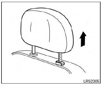
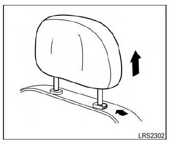
Raise
To raise the head restraint/headrest, pull it up.
Make sure the head restraint/headrest is positioned so the lock knob is engaged in the notch before riding in that designated seating position.
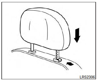
Lower
To lower, push and hold the lock knob and push the head restraint/headrest down.
Make sure the head restraint/headrest is positioned so the lock knob is engaged in the notch before riding in that designated seating position.
 Folding rear seat
Pull the knob A to fold each seatback down.
WARNING
Never allow anyone to ride in the cargo
area or on the rear seat when it is in the
fold-down position. Use of these areas
...
 Seat belts
...
Other materials:
Front wiper auto stop signal circuit
Component function check
1. Check front wiper (auto stop) operation
Consult data monitor
Select “WIP AUTO STOP” of IPDM E/R DATA MONITOR item.
Operate the front wiper.
With the front wiper operation, check the monitor status.
Is the inspection result normal?
YES >> ...
EPS branch line circuit
Diagnosis procedure
1.Check connector
Turn the ignition switch off.
Disconnect the battery cable from the negative terminal.
Check the terminals and connectors of the EPS control unit for damage,
bend and loose connection (unit
side and connector side).
Is the inspection result norm ...
Checking bulbs
With all doors closed, apply the parking brake
and place the ignition switch in the ON position
without starting the engine. The following lights
will come on:
If equipped, the following lights come on briefly
and then go off:
If any light fails to come on, it may indicate
an open circuit ...
