Nissan Sentra Service Manual: Front wiper and washer system
Component Parts Location
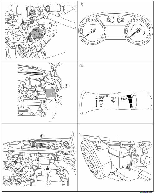
- BCM (view under instrument panel, left side of vehicle)
- Combination meter
- IPDM E/R (view with air inlet duct removed)
- Combination switch (wiper and washer switch)
- Front wiper motor (with wiper cowl cover removed)
- Front washer motor (with front bumper removed)
Component Description
| Part | Description |
| Combination meter | Transmits the vehicle speed signal to BCM with CAN communication. |
| BCM |
|
| IPDM E/R |
|
| Combination switch (Wiper and washer switch) |
|
| Front washer motor | Washer fluid is sprayed according to combination switch signal. |
| Front wiper motor |
|

 System
System Diagram
System Description
FRONT WIPER CONTROL (BASIC)
BCM detects the combination switch position by the combination switch
reading function.
BCM transmits the front wiper requ ...
Other materials:
OIL
Description
MAINTENANCE OF OIL LEVEL
The compressor oil is circulating in the system together with the
refrigerant. It is necessary to fill compressor
with oil when replacing A/C system parts or when a large amount of refrigerant
leakage is detected. It is important
to always maintain oil l ...
Component parts
Component parts location
Bcm (view with instrument panel removed)
Ipdm e/r (rear window defogger relay)
A/c auto amp. (View with a/c switch
assembly removed)
A/C switch assembly (rear window defogger
switch) (with auto A/C)
A/c switch assembly (rear window
defogger switch) (wit ...
P0131 A/F Sensor 1
DTC Logic
DTC DETECTION LOGIC
To judge the malfunction, the diagnosis checks that the A/F signal computed
by ECM from the A/F sensor 1
signal is not inordinately low.
DTC No.
CONSULT screen terms
(Trouble diagnosis content)
DTC detecting condition
Possible cause
P01 ...
