Nissan Sentra Service Manual: Front combination lamp
Exploded View
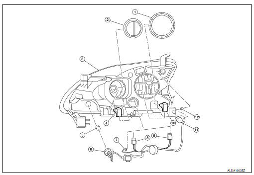
- Large cover (not serviceable)
- Small cover (not serviceable)
- Front combination lamp
- Halogen lamp bulb (high beam)
- Turn signal lamp bulb
- Turn signal lamp bulb socket
- LED harness connector
- Halogen lamp bulb (high beam) harness connector
- Halogen lamp bulb (low beam) harness connector
- Halogen lamp bulb (low beam)
- Side marker lamp bulb socket
- Side marker lamp bulb
Disassembly and Assembly
DISSASSEMBLY
WARNING:
Do not touch bulb while it is lit or right after being turned off. Burning may result.
CAUTION:
- Do not touch glass surface of the bulb with bare hands or allow oil or grease to get on it to prevent damage to bulb.
- Do not leave the bulb out of the lamp reflector for a long time
because dust, moisture, smoke, etc.
may affect the performance of the lamp.
- Remove front combination lamp. Refer to EXL-119, "Removal and Installation".
- Rotate the covers counterclockwise and remove.
- Rotate the halogen lamp bulb (low beam) counterclockwise and remove.
- Disconnect the harness connector from the halogen lamp bulb (low beam) and remove.
- Rotate the halogen lamp bulb (high beam) counterclockwise and remove.
- Disconnect the harness connector from the halogen lamp bulb (high beam) and remove.
- Rotate the side marker bulb socket counterclockwise and remove.
- Remove the side marker bulb from the side marker bulb socket.
- Rotate the turn signal bulb socket counterclockwise and remove.
- Remove the turn signal bulb from the turn signal bulb socket.
- Disconnect the harness connector from the LED circuit board and remove the harness.
ASSEMBLY
Assembly is in the reverse order of disassembly.
CAUTION:
After installing, be sure to install the bulb sockets securely to ensure watertightness.
Revision:

 Rear combination lamp
Exploded View
Rear combination lamp
Rear turn signal lamp bulb
Rear turn signal lamp socket
LED lamp harness connector
Rear combination lamp harness
connector
Back-up lamp bulb s ...
Other materials:
Removal and installation
ACCELERATOR CONTROL SYSTEM
Exploded View
Accelerator pedal assembly
Brake pedal bracket
Locating hook
Locating pin
Removal and Installation
REMOVAL
Remove instrument lower panel LH. Refer to IP-21, "Removal and
Installation".
Disconnect the harness connector ...
Trouble diagnosis - specification
value
Description
The specification (SP) value indicates the tolerance of the value that is
displayed in “SPEC” of “DATA MONITOR”
mode of CONSULT during normal operation of the Engine Control System. When the
value in “SPEC” of
“DATA MONITOR” mode is within t ...
Periodic maintenance
FUEL SYSTEM
Inspection
Inspect fuel lines, fuel filler cap, and fuel tank for improper attachment,
leakage, cracks, damage, loose connections, chafing or deterioration.
Engine
Fuel line
Fuel tank
If necessary, repair or replace damaged parts.
Quick Connector
CAUTION:
After c ...
