Nissan Sentra Service Manual: Engine assembly M/T
M/T : Exploded View
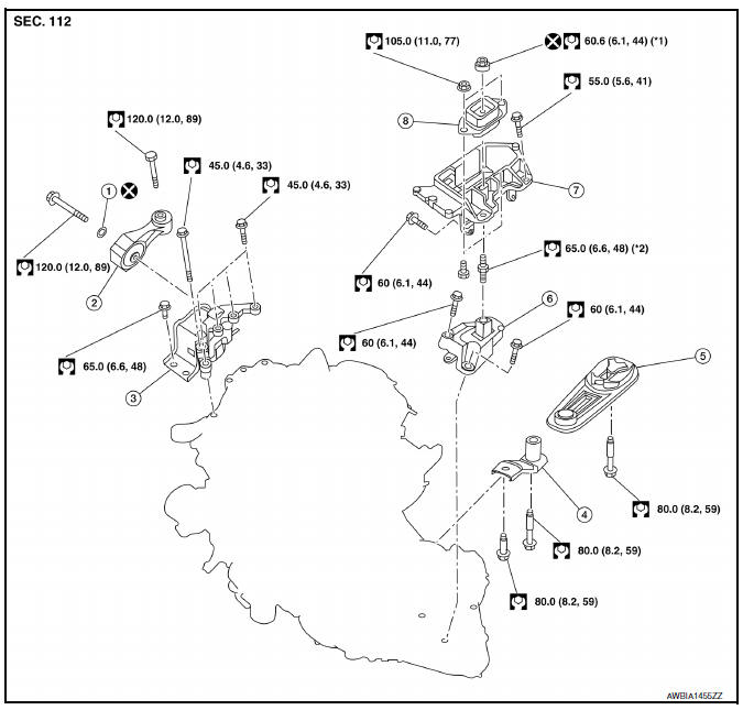
- Washer
- Upper torque rod (RH)
- Engine mounting insulator (RH)
- Rear torque rod bracket
- Rear torque rod
- Engine mounting bracket (LH)
- Engine mounting frame support (LH)
- Engine mounting insulator (LH)
CAUTION:
Check that the stud bolt (*2) is tight at the specified torque before tightening the nut (*1) shown. [Stud bolt (*2) may be loosened after loosening the nut (*1)]
M/T : Removal and Installation
WARNING:
- Situate the vehicle on a flat and solid surface.
- Place chocks at front and back of rear wheels.
- Attach proper slingers and bolts described in PARTS CATALOG if engine slingers are not equipped.
CAUTION:
- Always be careful to work safely, avoid forceful or uninstructed operations.
- Do not start working until exhaust system and coolant are cool enough.
- If items or work required are not covered by the engine section, refer to the applicable sections.
- Always use the support point specified for lifting.
- Use either 2-pole lift type or separate type lift as best you can. If board-on type is used for unavoidable reasons, support at the rear axle jacking point with a transmission jack or similar tool before starting work, in preparation for the backward shift of center of gravity
- For supporting points for lifting and jacking point at rear axle, refer to GI-31, "Garage Jack and Safety Stand and 2-Pole Lift".
NOTE:
When removing components such as hoses, tubes/lines, etc., cap or plug openings to prevent fluid from spilling.
REMOVAL
Outline
Remove the engine and the transaxle assembly from the vehicle downward. Separate the engine and the transaxle.
- Remove hood assembly. Refer to DLK-149, "HOOD ASSEMBLY : Removal and Installation".
- Release fuel pressure. Refer to EC-143, "Work Procedure".
- Remove battery and battery tray. Refer to PG-50, "Exploded View".
- Remove engine room cover. Refer to EM-24, "Exploded View".
- Remove cowl top. Refer to EXT-26, "Removal and Installation".
- Remove air cleaner body. Refer to EM-25, "Exploded View".
- Remove engine under cover. Refer to EM-24, "Exploded View".
- Drain engine coolant from radiator. Refer to CO-12, "Changing Engine Coolant".
CAUTION:
- Perform this step when the engine is cold.
- Do not spill engine coolant on drive belts.
- Remove front wheels and tires (RH/LH) using power tool. Refer to WT-47, "Adjustment".
- Remove front fender protector side covers (RH/LH). Refer to EXT-27, "FENDER PROTECTOR : Exploded View".
- Remove drive belt. Refer to EM-15, "Removal and Installation".
- Disconnect vacuum hose from intake manifold. Refer to EM-27, "Exploded View".
- Remove radiator hoses (upper and lower). Refer to CO-15, "Exploded View".
- Remove radiator and fan motor and shroud assembly. Refer to CO-15, "Exploded View".
- Remove ECM bracket, and then temporarily secure the engine harness on the engine side.
CAUTION:
Protect harness connectors using a resin bag against foreign materials during the operation.
- Disconnect fuel feed hose quick connector. Refer to EM-40, "Exploded View".
- Disconnect heater hoses. Refer to CO-24, "Exploded View".
- Disconnect control linkage from transaxle. Refer to TM-22, "Exploded View".
- Remove EVAP hoses. Refer to FL-14, "Exploded View".
- Disconnect clutch tube on transaxle side from concentric slave cylinder (CSC). Refer to CL-14, "Exploded View".
- Remove A/C compressor bolts and position A/C compressor aside. Refer to HA-30, "Exploded View".
- Remove ground cable at engine side.
- Remove ground cable at transaxle side.
- Remove drive shafts (RH/LH). Refer to FAX-18, "6M/T : Exploded View (LH)".
- Remove exhaust front tube. Refer to EX-5, "Exploded View".
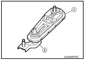
- Remove rear torque rod (1) and torque rod bracket (2).
- Remove stabilizer connecting rod. Refer to FSU-12, "Exploded View".
- Remove front suspension member. Refer to FSU-16, "Exploded View".
- Preparation for the separation work of transaxle is as follows:
- Remove transaxle joint bolts which pierce at oil pan (upper) lower rear side. Refer to EM-33, "Exploded View".
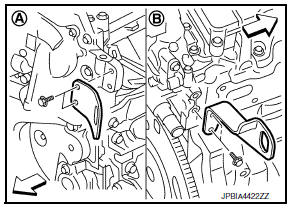
- Install engine slinger to front cover front (LH) side (A) and cylinder head rear (RH) side (B).
Slinger bolts
Front cover front (LH) side: : 32.9 NВ·m (3.4 kg-m, 24 ft-lb)
Cylinder head rear (RH) side: : 25.0 NВ·m (2.6 kg-m, 18 ft-lb)
- Support engine and transaxle assembly with engine lifting equipment from the top with the vehicle raised on a hoist.
- Use a manual lift table caddy (A) or equivalent rigid tool such as a transmission jack. Securely support bottom of the engine and the transaxle assembly.
CAUTION:
Put a piece of wood or equivalent as the supporting surface, secure a completely stable condition.
- Remove upper torque rod (1) and engine mounting insulator (RH) (2).
- Remove engine mounting bracket (LH) through bolt nut (B).
(1) : Engine mounting insulator (LH)
(2) : Engine mounting bracket support (LH)
(A) : Through bolt
- Carefully lower jack, or raise lift to remove the engine and the transaxle assembly. When performing work, observe the following caution.
CAUTION:
- Check that no part interferes with the vehicle side.
- Before and during this lifting, always check if any harnesses are left connected.
- During the removal, always be careful to prevent the vehicle from falling off the lift due to changes in the center of gravity.
- If necessary, support the vehicle by setting jack or suitable tool at the rear.
- Remove starter motor. Refer to STR-30, "Exploded View".
- Lift with a hoist and separate the engine from the transaxle assembly. Refer to TM-28, "Exploded View".
INSTALLATION
Installation is in the reverse order of removal.
NOTE:
Tighten all mounts to specification.
CAUTION:
- Do not allow engine oil to get on engine insulator. Be careful not to damage engine mounting insulator.
- Check that each mounting insulator is seated properly, and tighten nuts and bolts.
- When installation directions are specified, install parts according to the direction marks on them referring to the illustration of components. Refer to EM-82, "M/T : Exploded View".
M/T : Inspection
INSPECTION AFTER INSTALLATION
- Before starting engine, check oil/fluid levels including engine coolant and engine oil. If less than required quantity, fill to the specified level. Refer to MA-11, "Fluids and Lubricants".
- Use procedure below to check for fuel leakage.
- Turn ignition switch “ON” (with engine stopped). With fuel pressure applied to fuel piping, check for fuel leakage at connection points.
- Start engine. With engine speed increased, check again for fuel leakage at connection points.
- Run engine to check for unusual noise and vibration.
NOTE:
If hydraulic pressure inside timing chain tensioner drops after removal and installation, slack in the guide may generate a pounding noise during and just after engine start. However, this is normal. Noise will stop after hydraulic pressure rises.
- Warm up engine thoroughly to check there is no leakage of fuel, exhaust gases, or any oil/fluids including engine oil and engine coolant.
- Bleed air from lines and hoses of applicable lines, such as in cooling system.
- After cooling down engine, again check oil/fluid levels including engine oil and engine coolant. Refill to the specified level, if necessary.
- Summary of the inspection items:
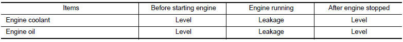
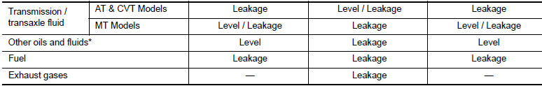
*: Power steering fluid, brake fluid, etc.

 Engine assembly CVT
CVT : Exploded View
Washer
Upper torque rod (RH)
Engine mounting insulator (RH)
Engine mounting insulator (LH)
Rear torque rod bracket
Rear torque rod
CVT : Removal and Installati ...
Other materials:
Engine oil
Inspection
Engine oil level
Note:
Before starting engine, put vehicle horizontally and check the engine oil
level. If engine is already started, stop
it and allow 10 minutes before checking.
Pull out oil level gauge and wipe it clean.
Insert oil level gauge and check that the engine oil ...
Front seat belt
Exploded View
D-ring anchor
Seat belt height adjuster cover
Seat belt buckle
Seat belt retractor
Seat belt height adjuster
Lap belt pre-tensioner harness
connector
Shoulder belt pre-tensioner
harness connector
Front
NOTE:
LH side shown; RH side similar.
Removal an ...
Uniform tire quality grading
DOT (Department of Transportation) Quality
Grades: All passenger car tires must conform to
federal safety requirements in addition to these
grades.
Quality grades can be found where applicable on
the tire sidewall between tread shoulder and
maximum section width. For example:
Treadwear 200 ...
