Nissan Sentra Service Manual: Ecu diagnosis information
Bcm, ipdm e/r
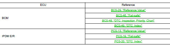
List of ecu reference
 Diagnosis system (BCM)
Common item
Common item : consult function (bcm - common item)
Application item
Consult performs the following functions via can communication with bcm.
System application
Bcm can perform the ...
 Wiring diagram
Power distribution system
Wiring diagram
...
Other materials:
Text messaging
WARNING
Laws in some jurisdictions may restrict
the use of some of the applications and
features, such as social networking and
texting.
Laws in some jurisdictions may restrict
the use of “Text-to-Speech”. Check local
regulations before using this
feature.
...
Precaution
Precaution for supplemental restraint system (srs) "air bag" and "seat
belt pre-tensioner"
The Supplemental Restraint System such as “AIR BAG” and “SEAT BELT PRE-TENSIONER”,
used along
with a front seat belt, helps to reduce the risk or severity of injur ...
Basic inspection
Diagnosis and repair workflow
Trouble diagnosis flow chart
Trouble diagnosis procedure
Interview with customer
Interview with the customer is important to detect the root cause of can
communication system errors and to
understand vehicle condition and symptoms for proper trouble diagnosi ...
