Nissan Sentra Service Manual: Basic inspection
Diagnosis and repair workflow
Trouble diagnosis flow chart
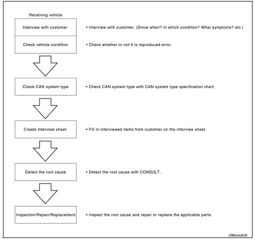
Trouble diagnosis procedure
Interview with customer
Interview with the customer is important to detect the root cause of can communication system errors and to understand vehicle condition and symptoms for proper trouble diagnosis.
Points in interview
- What: parts name, system name
- When: date, frequency
- Where: road condition, place
- In what condition: Driving condition/environment
- Result: symptom
Notes for checking error symptoms:
- Check normal units as well as error symptoms.
Example: Circuit between ECM and the combination meter is judged normal if the customer indicates tachometer functions normally.
- When a can communication system error is present, multiple control units may malfunction or go into failsafe mode.
- Indication of the combination meter is important to detect the root cause because it is the most obvious to the customer, and it performs CAN communication with many units.
Inspection of vehicle condition
Check whether the symptom is reproduced or not.
Note:
Do not turn the ignition switch off or disconnect the battery cable while reproducing the error. The error may temporarily correct itself, making it difficult to determine the root cause.
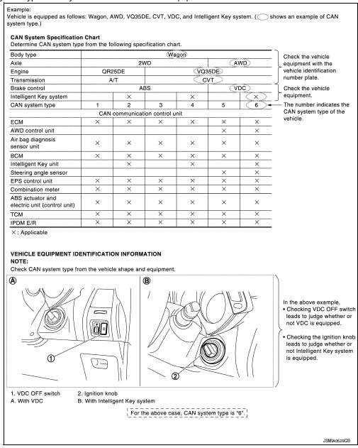
Check of can system type (how to use can system type specification chart)
Determine can system type based on vehicle equipment.
Note:
- This chart is used if consult does not automatically recognize can system type.
- There are two styles for can system type specification charts. Depending on the number of available system types, either style a or style b may be used.
CAN System Type Specification Chart (Style A)
Note:
Can system type is easily checked with the vehicle equipment identification information shown in the chart.
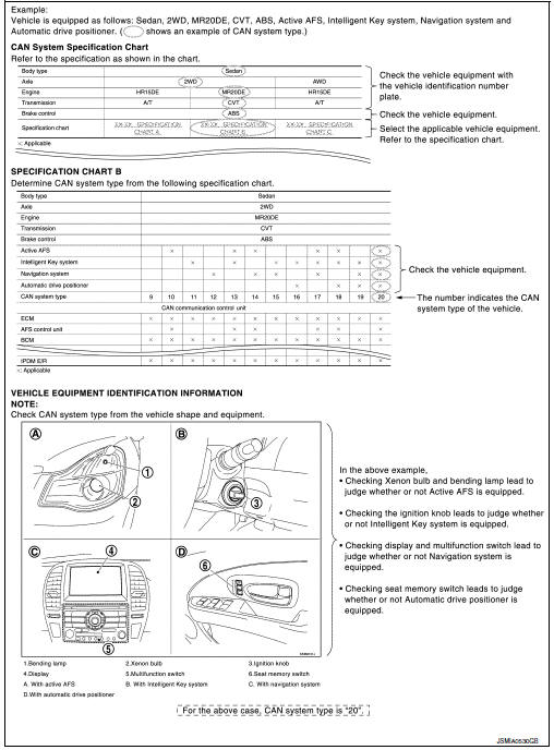
Can system type specification chart (style b)
Note:
Can system type is easily checked with the vehicle equipment identification information shown in the chart.
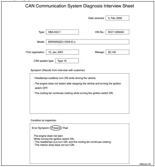
Create interview sheet
Fill out the symptom described by the customer, vehicle condition, and can system type on the interview sheet.
Interview sheet (example)
Detect the root cause
Can diagnosis function of consult detects the root cause.
 System description
System
Can communication system
Can communication system : system description
CAN (Controller Area Network) is a serial communication line for real time
application. It is an on-vehicle multiplex ...
 Can
Can
...
Other materials:
Inside key antenna
Console
CONSOLE : Removal and Installation
REMOVAL
Remove the shift selector finisher. Refer to IP-17, "Removal and
Installation".
Remove the inside key antenna (console) screws (A) and inside
key antenna (console) (1).
INSTALLATION
Installation is in the reverse order ...
Wiper blade
Wiper blade
WIPER BLADE : Removal and Installation
REMOVAL
Put the wiper arms in the service position.
Turn the ignition switch ON and then OFF.
Within 1 minute, activate washer switch 2 times in less than 0.5 seconds
to put the wiper arms in the service
position.
Lift the w ...
Wheel side
WHEEL SIDE : Removal and Installation
REMOVAL
Remove the wheel and tire using power tool. Refer to WT-47, "Exploded
View".
Remove the brake caliper torque member bolts, leaving the brake hose
attached. Position the brake caliper
aside with wire. Refer to BR-41, "BRAKE C ...
