Nissan Sentra Service Manual: Ecm branch line circuit
Diagnosis Procedure
1.Check connector
- Turn the ignition switch off.
- Disconnect the battery cable from the negative terminal.
- Check the terminals and connectors of the ECM for damage, bend and loose connection (unit side and connector side).
Is the inspection result normal? YES >> GO TO 2.
NO >> Repair the terminal and connector.
2.Check harness for open circuit
- Disconnect the connector of ECM.
- Check the resistance between the ecm harness connector terminals.
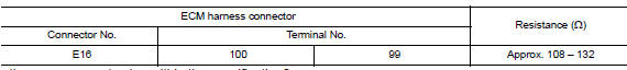
Is the measurement value within the specification? Yes >> go to 3.
No >> repair the ecm branch line.
3.Check power supply and ground circuit
Check the power supply and the ground circuit of the ecm. Refer to ec-164, "diagnosis procedure".
Is the inspection result normal? Yes (present error)>>replace the ecm. Refer to ec-485, "removal and installation".
Yes (past error)>>error was detected in the ecm branch line.
No >> repair the power supply and the ground circuit.
 Main line between dlc and hvac circuit
Diagnosis Procedure
1.Check harness continuity (open circuit)
Turn the ignition switch OFF.
Disconnect the battery cable from the negative terminal.
Disconnect the following harness connector ...
 Abs branch line circuit
Diagnosis procedure
1.CHECK CONNECTOR
Turn the ignition switch OFF.
Disconnect the battery cable from the negative terminal.
Check the terminals and connectors of the ABS actuator and electri ...
Other materials:
Door lock actuator
Driver side
Driver side : component function check
1.CHECK FUNCTION
Select DOOR LOCK of BCM using CONSULT.
Select DOOR LOCK in ACTIVE TEST mode.
Touch ALL LOCK or ALL UNLK to check that it works normally.
Is the inspection result normal?
YES >> Door lock actuator is OK.
NO > ...
System description
Component parts
Component parts location
Instrument lower finisher
Sport mode switch
The sport mode switch is installed to the instrument lower finisher.
When the sport mode indicator lamp on the combination meter
is off and the sport mode switch is pressed, the sport mode
is ...
Brake booster
Inspection
Operation
Depress the brake pedal several times at five second intervals with
the engine stopped. Start the engine with the brake pedal fully
depressed. Check that the clearance between brake pedal and dash
lower panel decreases.
NOTE:
A slight impact with a small click may be felt ...
