Nissan Sentra Service Manual: Dtc/circuit diagnosis
Eco mode switch
Component function check
1. Check eco mode switch operation
- Turn ignition switch ON.
- Check ECO mode indicator lamp turns ON/OFF on combination meter when turn ECO mode switch ON/ OFF.
Is the inspection result normal? Yes >> inspection end
No >> go to dms-38, "diagnosis procedure".
Diagnosis procedure
Regarding wiring diagram information, refer to dms-28, "wiring diagram".
1.Detect malfunctioning items
What is malfunction items? Eco mode switch illumination does not turns on>>go to 2.
Eco mode indicator lamp does not turns on>>go to 8.
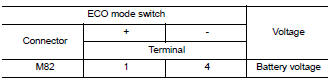
2.Check eco mode switch illumination power supply (1)
- Turn off the headlamp.
- Turn ignition switch OFF
- Disconnect ECO mode switch harness connector
- Turn ignition switch on.
- Turn ON the headlamp
- Check the voltage between eco mode switch harness connector terminals.
Is the inspection result normal? Yes >> go to 3.
No >> go to 4.
3.Check intermittent incidente
Refer to gi-39, "intermittent incident".
Is the inspection result normal? Yes >> replace eco mode switch. Refer to dms-39, "removal and installation".
No >> replace the fuse after repair the applicable circuit.
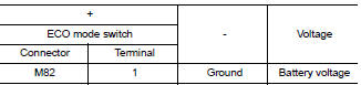
4.Check eco mode switch illumination power supply (2)
Check the voltage between ECO mode switch harness connector and ground.
Is the inspection result normal? Yes >> go to 7.
No >> go to 5.
5.Check fuse
- Turn off the headlamp.
- Turn ignition switch OFF.
- Pull out #37 fuse. Refer to pg-47, "terminal arrangement".
- Check that the fuse is not fusing.
Is the inspection result normal? Yes >> go to 6.
No >> replace the fuse after repair the applicable circuit.
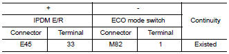
6.Check eco mode switch illumination power supply circuit
- Disconnect IPDM E/R harness connector E45. Refer to INL-26, "Wiring Diagram".
- Check the continuity between ipdm e/r harness connector and eco mode switch harness connector
- Also check harness for short to ground.
Is the inspection result normal? Yes >> perform ipdm e/r auto active test and check tail lamp relay operation. Refer to pcs-9, "diagnosis description" (with intelligent key), pcs-37, "diagnosis description" (without intelligent key).
No >> repair or replace error-detected parts.
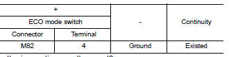
7.Check ground circuit
- Turn off the headlamp.
- Turn ignition switch off.
- Check continuity between eco mode switch harness connector terminal and ground.
Is the inspection result normal? Yes >> check intermittent incident. Refer to gi-39, "intermittent incident".
No >> repair or replace error-detected parts.
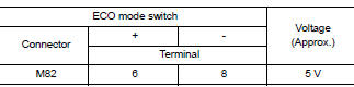
8.Check eco mode switch circuit
- Turn ignition switch off
- Disconnect eco mode switch harness connector.
- Turn ignition switch on.
- Check voltage between eco mode switch harness connector terminals
Is the inspection result normal? Yes >> go to 13.
No >> go to 9.
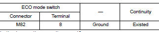
9.Check ground circuit
- Turn ignition switch off.
- Check the continuity between eco mode switch harness connector and ground.
Is the inspection result normal? YES >> GO TO 10.
NO >> Repair or replace damaged parts.
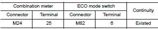
10.Check circuit between combination meter and eco mode switch (1)
- Disconnect combination meter harness connector M24.
- Check continuity between combination meter harness connector terminal and eco mode switch harness connector terminal
Is the inspection result normal? YES >> GO TO 11.
NO >> Repair or replace damaged parts.
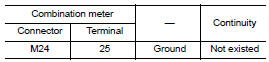
11.Check circuit between combination meter and eco mode switch (2)
Check continuity between combination meter harness connector terminal and ECO mode switch harness connector terminal.
Is the inspection result normal? Yes >> go to 12.
No >> repair or replace damaged parts.
12.Check combination meter input/output signal
- Connect all of disconnected connectors.
- Check input/output signal of combination meter. Refer to MWI-20, "Reference Value".
Is the inspection result normal? Yes >> check intermittent incident. Refer to gi-39, "intermittent incident".
No >> replace combination meter. Refer to mwi-77, "removal and installation".
13.Check eco mode switch
Check eco mode switch. Refer to dms-37, "component inspection".
Is the inspection result normal?
Yes >> check intermittent incident. Refer to gi-39, "intermittent incident".
No >> replace eco mode switch. Refer to dms-39, "removal and installation".
Component inspection
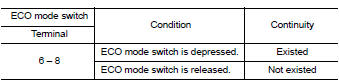
1.Check eco mode switch
Check continuity between eco mode switch connector terminals.
Is the inspection result normal? YES >> INSPECTION END
NO >> Replace ECO mode switch. Refer to DMS-39, "Removal and Installation".
 Basic inspection
Diagnosis and repair work flow
Work flow
Detailed flow
1.Obtain information about symptom
Interview the customer to obtain as much information as possible about the
conditions and environment un ...
 Symptom diagnosis
The eco mode indicator lamp does not turn on
Description
The ECO mode indicator lamp does not turn ON when the ECO mode switch is
operated.
Diagnosis Procedure
1.Perform combination meter on boa ...
Other materials:
Basic inspection
Diagnosis and repair work flow
Work flow
Detailed flow
1.Obtain information about symptom
Interview the customer to obtain as much information as possible about the
conditions and environment under
which the malfunction occurs.
>> GO TO 2.
2.Check symptom
Check the symptom based ...
Receiving a call
When a call is placed to the connected phone,
the display will change to phone mode.
To accept the incoming call, either:
Press the button on
the steering
wheel, or
Touch the green phone icon on the screen.
To reject the incoming call, either:
Press the button on the
...
Precautions on seat belt usage
If you are wearing your seat belt properly adjusted
and you are sitting upright and well back in
your seat with both feet on the floor, your chances
of being injured or killed in an accident and/or the
severity of injury may be greatly reduced.
NISSAN strongly encourages you and all of yo ...
