Nissan Sentra Service Manual: Dtc/circuit diagnosis
U1000 can comm
Description
Refer to LAN-7, "CAN COMMUNICATION SYSTEM : System Description".
Dtc logic
Dtc detection logic
Note:
U1000 can be set if a module harness was disconnected and reconnected, perhaps during a repair. Confirm that there are actual can diagnostic symptoms and a present dtc by performing the self diagnostic result procedure.
| Consult display | Dtc detection condition | Possible cause |
| Can comm circuit [u1000] | When any listed module cannot communicate with can communication signal continuously for 2 seconds or more with ignition switch on | In CAN communication system, any item (or
items) of the following listed below is malfunctioning.
|
Diagnosis procedure
1. Perform self diagnostic result
- Turn ignition switch ON and wait for 2 second or more.
- Check “self- diag results”.
Is “can comm circuit” displayed? Yes >> perform can diagnosis as described in diagnosis section of consult operation manual.
No >> refer to gi-39, "intermittent incident".
U1010 control unit (can)
Dtc logic
Dtc detection logic
| Consult display | Dtc detection condition | Possible cause |
| Control unit (can) [u1010] | Bcm detected internal can communication circuit malfunction. | Bcm |
Diagnosis procedure
1.Replace bcm
When dtc “u1010” is detected, replace bcm.
>> Replace bcm. Refer to bcs-126, "removal and installation".
Power supply and ground circuit
Diagnosis procedure
Regarding wiring diagram information, refer to bcs-111, "wiring diagram".
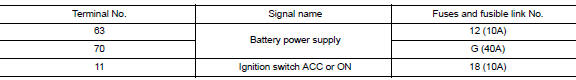
1.Check fuses and fusible link
Check that the following fuses and fusible link are not blown.
Is the fuse blown? Yes >> replace the blown fuse or fusible link after repairing the affected circuit.
No >> go to 2.
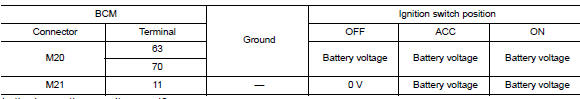
2.Check power supply circuit
- Turn ignition switch off.
- Disconnect bcm connectors.
- Check voltage between bcm connector and ground.
Is the inspection result normal? Yes >> go to 3.
No >> repair harness or connector.
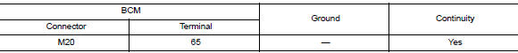
3.Check ground circuit
Check continuity between bcm connector and ground.
Is the inspection result normal? Yes >> inspection end.
No >> repair harness or connector.
Combination switch input circuit
Diagnosis procedure
Regarding wiring diagram information, refer to bcs-111, "wiring diagram".
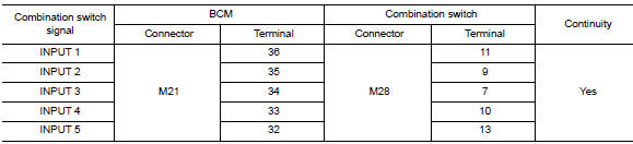
1.Check input 1 - 5 circuit for open
- Turn ignition switch OFF.
- Disconnect bcm and combination switch connectors.
- Check continuity between BCM connector and combination switch connector.
Is the inspection result normal? Yes >> go to 2.
No >> repair harness or connectors.
2.Check input 1 - 5 circuit for short
Check for continuity between bcm connector and ground.
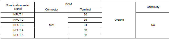
Is the inspection result normal? Yes >> repair harness or connectors.
No >> go to 3.
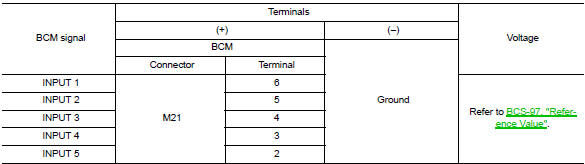
3.Check bcm output voltage
- Connect BCM connector.
- Check voltage between bcm connector and ground.
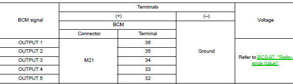
Is the inspection result normal? Yes >> replace combination switch.
No >> replace bcm. Refer to bcs-126, "removal and installation".
Combination switch output circuit
Diagnosis procedure
Regarding Wiring Diagram information, refer to BCS-111, "Wiring Diagram".
1.Check output 1 - 5 circuit for open
- Turn ignition switch off.
- Disconnect bcm and combination switch connectors.
- Check continuity between bcm connector and combination switch connector.
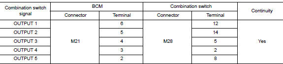
Is the inspection result normal? Yes >> go to 2.
No >> repair harness or connectors.
2.Check output 1 - 5 circuit for short
Check for continuity between bcm connector and ground.
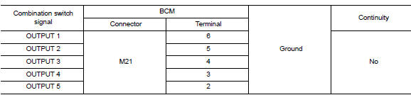
Is the inspection result normal? Yes >> repair harness or connectors.
No >> go to 3.
3.Check bcm input signal
- Connect BCM and combination switch connectors.
- Turn on any switch in the system that is malfunctioning.
- Check voltage between bcm connector and ground.
Is the inspection result normal? Yes >> replace bcm. Refer to bcs-126, "removal and installation".
No >> replace combination switch.
 Basic inspection
Inspection and adjustment
Additional service when replacing control unit (bcm)
Additional service when replacing control unit (bcm) : description
Before replacement
When replacing BCM, save or pr ...
 Symptom diagnosis
Combination switch system symptoms
Symptom Table
Perform the data monitor of consult to check for any malfunctioning
item.
Check the malfunction combinations.
Identify the malfunct ...
Other materials:
Front door finisher
Exploded View
Front door panel
Front door finisher
Inside door handle escutcheon
Main power window and door lock/
unlock switch finisher
Door mirror corner finisher
Grommet
Clip
Pawl
Front
NOTE:
LH side shown; RH similar.
Removal and Installation
CAUTION:
When ...
Removal and installation
Bcm (body control module)
Removal and Installation
Note:
Before replacing bcm, perform “read configuration” to save or print
current vehicle specification. Refer
to bcs-116, "configuration (bcm) : description".
Removal
Disconnect the negative battery terminal. Refer to ...
Passenger side door mirror defogger
Description
Heats the heating wire with the power supply from the rear window defogger
relay to prevent the door mirror
from fogging up.
Component function check
1.Check door mirror defogger rh
Check that the heating wire of door mirror defogger rh is heated when turning
the rear window de ...
