Nissan Sentra Owners Manual: Difference between predicted and actual distances
The distance guide line and the vehicle width guide line should be used as a reference only when the vehicle is on a level, paved surface. The distance viewed on the monitor is for reference only and may be different than the actual distance between the vehicle and displayed objects.
Backing up on a steep uphill
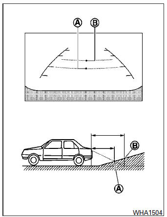
When backing up the vehicle up a hill, the distance guide lines and the vehicle width guide lines are shown closer than the actual distance.
For example, the display shows 3 ft (1.0 m) to the place A , but the actual 3 ft (1.0 m) distance on the hill is the place B . Note that any object on the hill is further than it appears on the monitor.
Backing up on a steep downhill
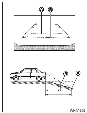
When backing up the vehicle down a hill, the distance guide lines and the vehicle width guide lines are shown farther than the actual distance.
For example, the display shows 3 ft (1.0 m) to the place A , but the actual 3 ft (1.0 m) distance on the hill is the place B . Note that any object on the hill is closer than it appears on the monitor.
Backing up behind a projecting object
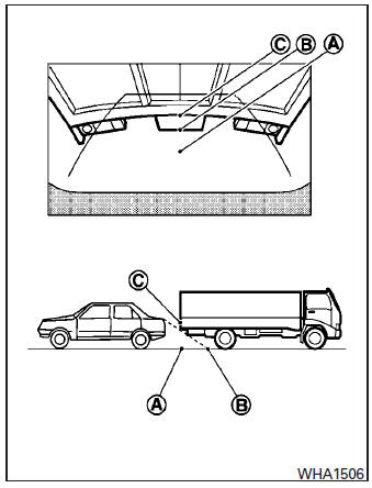
The position C is shown farther than the position B in the display. However, the position C is actually at the same distance as the position A .
The vehicle may hit the object when backing up to the position A if the object projects over the actual backing up course.
 How to read the displayed lines
Guiding lines which indicate the vehicle width
and distances to objects with reference to the
vehicle body line A are displayed on the monitor.
Distance guide lines:
Indicate distances from th ...
 Adjusting the screen
Without Navigation System
The procedure for adjusting the quality of the
screen differs depending on the type of screen
present on the vehicle.
For vehicles without Navigation System:
Pr ...
Other materials:
Door sash tape
Exploded view
Front door sash upper tape
Front door assembly
Rear door assembly
Front door sash rear tape
Rear door sash front tape
Rear door sash rear tape
Rear door sash upper tape
Front door sash tape
FRONT DOOR SASH TAPE : Removal and Installation
REMOVAL
Heat door sash ...
System description
Component parts
POWER DOOR LOCK SYSTEM
POWER DOOR LOCK SYSTEM : Component Parts Location
BCM (view with instrument panel removed)
Front door switch LH
Front door lock actuator LH
Front door lock assembly LH
Front door switch RH
Front door lock actuator RH
Rear door switch RH
...
Ecu diagnosis information
Bcm (body control module)
List of ecu reference
Moonroof motor assembly
Reference value
Terminal layout
Physical values
...
