Nissan Sentra Service Manual: Description
| Number | Item | Description |
| 1 | Power supply |
|
| 2 | Fusible link |
|
| 3 | Number of fusible link/ fuse |
|
| 4 | Fuse |
|
| 5 | Current rating of fusible link/fuse |
|
| 6 | Optional splice |
|
| 7 | Connector number |
|
| 8 | Splice |
|
| 9 | Page crossing |
|
| 10 | Option abbreviation |
|
| 11 | Relay |
|
| 12 | Option description |
|
| 13 | Switch |
|
| 14 | Circuit (Wiring) |
|
| 15 | System branch |
|
| 16 | Shielded line |
|
| 17 | Component name |
|
| 18 | Ground (GND) |
|
| 19 | Connector |
|
| 20 | Connectors |
|
| 21 | Wire color |
|
| B = Black W = White R = Red G = Green L = Blue Y = Yellow LG = Light Green BG = Beige BR = Brown LA = Lavender OR or O = Orange P = Pink PU or V (Violet) = Purple GY or GR = Gray SB = Sky Blue CH = Dark Brown DG = Dark Green |
||
|
||
| 22 | Terminal number |
|

 ”.
”.Switch positions
Switches are shown in wiring diagrams as if the vehicle is in the “normal” condition.
A vehicle is in the “normal” condition when:
- ignition switch is “OFF”,
- doors, hood and trunk lid/back door are closed,
- pedals are not depressed, and
- parking brake is released.
Multiple switch
The continuity of multiple switch is described in two ways as shown below.
- The switch chart is used in schematic diagrams.
- The switch diagram is used in wiring diagrams.
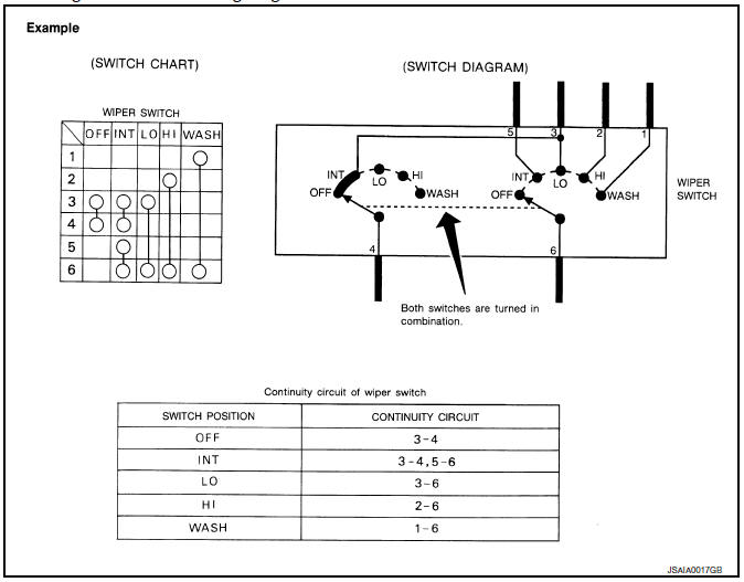
 Sample/wiring diagram -example-
For detail, refer to following GI-11, "Description".
...
 Abbreviations
Abbreviation List
The following ABBREVIATIONS are used:
A
ABBREVIATION
DESCRIPTION
A/C
Air conditioner
A/C
Air conditioning
A/F sensor
Air fuel ...
Other materials:
DTC/circuit diagnosis
POWER SUPPLY AND GROUND CIRCUIT
A/C AUTO AMP.
A/C AUTO AMP. : Diagnosis Procedure
Regarding Wiring Diagram information, refer to HAC-145, "Wiring Diagram" or
HAC-152, "Wiring Diagram".
1.CHECK FUSE
Check fuses [No. 5, 8 and 21, located in the fuse block (J/B)].
NOTE:
Ref ...
Precaution
Precaution for supplemental restraint system (srs) "air bag" and "seat belt
pre-tensioner"
The Supplemental Restraint System such as “AIR BAG” and “SEAT BELT PRE-TENSIONER”,
used along
with a front seat belt, helps to reduce the risk or severity of injur ...
Diagnosis description : permanent diagnostic
trouble code (permanent DTC)
Permanent DTC is defined in SAE J1979/ISO 15031-5 Service $0A.
ECM stores a DTC issuing a command of turning on MIL as a permanent DTC and
keeps storing the DTC as
a permanent DTC until ECM judges that there is no presence of malfunction.
Permanent DTCs cannot be erased by using the erase f ...
