Nissan Sentra Service Manual: Cylinder head
Exploded View
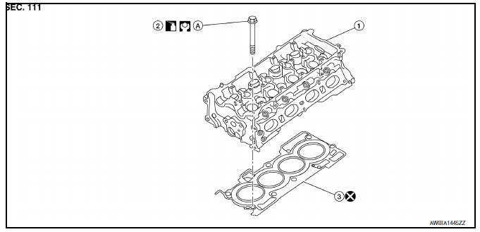
- Cylinder head assembly
- Cylinder head bolt
- Cylinder head gasket
- Refer to INSTALLATION
Removal and Installation
REMOVAL
- Release fuel pressure. Refer to EC-143, "Work Procedure".
- Drain engine coolant and engine oil. Refer to CO-12, "Changing Engine Coolant" (for Coolant) and LU-8, "Draining" (for Oil).
- Remove fan motor and shroud assembly. Refer to CO-17, "Component".
- Remove the exhaust manifold. Refer to EM-30, "Exploded View"
- Remove the intake manifold. Refer to EM-27, "Exploded View".
- Remove the fuel injector and fuel tube assembly. Refer to EM-40, "Exploded View".
- Remove the water outlet. Refer to CO-24, "Exploded View".
- Remove the rocker cover. Refer to EM-46, "Exploded View".
- Remove the front cover and timing chain. Refer to EM-48, "Exploded View".
- Remove the camshaft. Refer to EM-60, "Exploded View".
- Remove cylinder head.
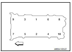
- Loosen cylinder head bolts in the reverse order as shown.
- Remove cylinder head gasket.
INSTALLATION
- Install cylinder head gasket.
CAUTION:
Do not reuse cylinder head gasket.
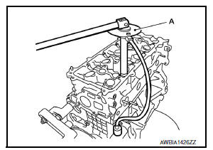
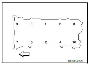
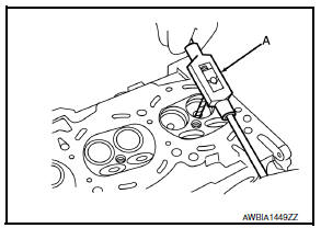
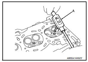
- Install cylinder head, and tighten cylinder head bolts in order as shown using Tool (A).
- Clean threads and seating surfaces of bolts.
- Apply new engine oil to threads and seating surface of bolts.
CAUTION:
- If cylinder head bolts are reused, check their outer diameters before installation. Refer to EM-79, "Inspection".
- Check and confirm the tightening angle by using Tool. Do not judge by visual inspection without the tool.
Tool number : KV10112100 (BT-8653-A)
Step 1 : 40.0 NВ·m (4.1 kg-m, 30 ft-lb)
Step 2 : 100В° clockwise in order
Step 3 : 0 NВ·m (0 kg-m, 0 ft-lb)
Step 4 : 40.0 NВ·m (4.1 kg-m, 30 ft-lb)
Step 5 : 100В° clockwise in order
Step 6 : 100В° clockwise in order
- Installation of remaining components is in the reverse order of removal.
Exploded View
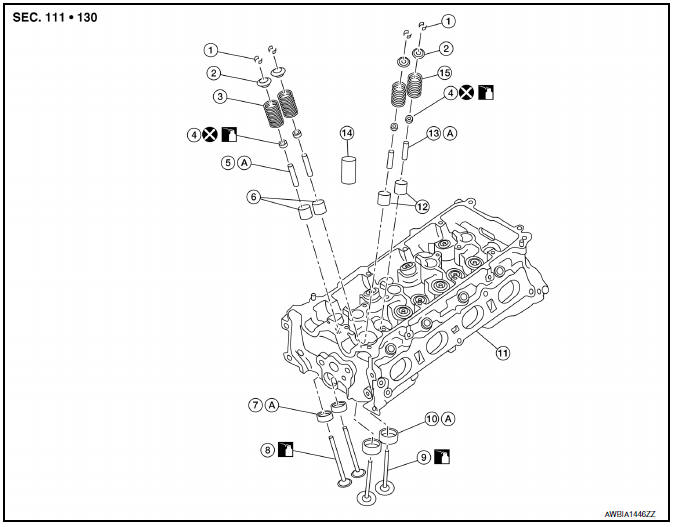
- Valve collet
- Valve spring retainer
- Valve spring (EXH) (with valve spring seat)
- Valve oil seal
- Valve guide (EXH)
- Valve lifter (EXH)
- Valve seat (EXH)
- Valve (EXH)
- Valve (INT)
- Valve seat (INT)
- Cylinder head
- Valve lifter (INT)
- Valve guide (INT)
- Spark plug tube
- Valve spring (INT) (with valve spring seat)
- Refer to INSTALLATION
Disassembly and Assembly
DISASSEMBLY
- Remove spark plug using suitable tool.
- Remove valve lifter.
- Identify installation positions, and store them without mixing them up.
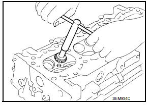
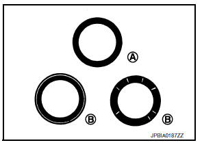
- Remove valve collet, valve spring retainer, and valve spring using Tools.
Tool number (A) : KV1016200 (J-26336-A)
Tool number (B) : KV10109220 ( — )
Tool number (C) : KV10115900 (J-26336-20)
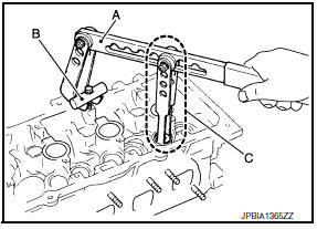
CAUTION:
- Do not damage valve lifter holes.
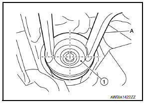
- Install Tool (A) in the center of valve spring retainer (1) to install it.
Tool number : KV10115900 (J-26336-20)
- Remove valve spring retainer and valve spring (with valve spring seat).
CAUTION:
Do not remove valve spring seat from valve spring.
- Push valve stem to combustion chamber side, and remove valve.
- Identify installation positions, and store them without mixing them up.
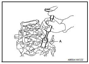
- Remove valve oil seal using Tool (A).
Tool number : KV10107902 (J-38959)
- Remove valve seat, if necessary
- Bore out old seat until it collapses. Boring should not continue beyond the bottom face of the seat recess in cylinder head. Set the machine depth stop to ensure this. Refer to EM-121, "Cylinder Head".
CAUTION:
Do not bore excessively to prevent damage to cylinder head.
- Remove valve guide, if necessary.
- To remove valve guide, heat cylinder head to 110 to 130В°C (230 to 266В°F) by soaking in heated oil (A).
WARNING:
Cylinder head contains heat. When working, wear protective equipment to avoid getting burned.
- Drive out valve guide using suitable tool.
ASSEMBLY
- Install valve guide, if removed.
CAUTION:
Replace with oversize [0.2 mm (0.008 in)] valve guide. Refer to EM-121, "Cylinder Head".
- Ream cylinder head valve guide hole using suitable tool (A).
- Heat cylinder head to 110 to 130В°C (230 to 266В°F) by soaking in heated oil (A).
WARNING:
Cylinder head contains heat. When working, wear protective equipment to avoid getting burned.
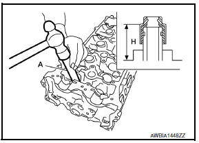
- Press valve guide (1) from camshaft side to dimension as shown.
(2) : Cylinder head
Projection (H) : Refer to EM-121, "Cylinder Head".
- Apply reamer finish to valve guide using suitable tool (A).
Standard : Refer to EM-121, "Cylinder Head".
- Install valve seat, if removed.
CAUTION:
Replace with oversize [0.5 mm (0.020 in)] valve seat. Refer to EM-121, "Cylinder Head".
- Ream cylinder head (1) recess diameter for service valve seat (2).
- Be sure to ream in circles concentric to the valve guide center.
This will enable valve seat to fit correctly.
- Heat cylinder head to 110 to 130В°C (230 to 266В°F) by soaking in heated oil (A).
WARNING:
Cylinder head contains heat. When working, wear protective equipment to avoid getting burned.
- Provide valve seats cooled well with dry ice. Press-fit valve seat into cylinder head.
CAUTION:
Do not touch cold valve seats directly.
- Finish valve seat to the specified dimension using suitable tool.
Refer to EM-121, "Cylinder Head".
CAUTION:
When using valve seat cutter, firmly grip the cutter handle with both hands. Then, press on the contacting surface all around the circumference to cut in a single drive. Improper pressure on the cutter or cutting many different times may result in stage valve seat.
- Using compound, grind to adjust valve.
- Check again for normal contact. Refer to EM-121, "Cylinder Head".
- Install valve oil seal using Tool (A).
NOTE:
Dimension is height measured before installing valve spring (with valve spring seat).
Height (H) : 15.1 - 15.7 mm (0.594 - 0.618 in)
Tool number : KV10115600 (J-38958)
- Install valve.
- Install larger diameter to intake side.
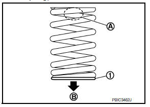
- Install valve spring with valve spring seat (1) (do not remove from valve spring).
- Install smaller pitch (valve spring seat side) to cylinder head side (B).
- Confirm identification color (A) of valve spring.
Intake : White
Exhaust : Orange
- Install valve spring retainer.
- Install valve collet.
- Compress valve spring using Tool. Install valve collet with a magnet hand.
Tool number (A) : KV1016200 (J-26336-A)
Tool number (B) : KV10109220 ( — )
Tool number (C) : KV10115900 (J-26336-20)

CAUTION:
When working do not damage valve lifter holes.
- Tap valve stem edge lightly with a plastic hammer after installation to check its installed condition.
- Install valve lifter.
- Install it in the original position.
- Install spark plug. Refer to EM-12, "Exploded View".
Inspection
INSPECTION AFTER REMOVAL
Cylinder Head Bolts Outer Diameter
- Cylinder head bolts are tightened by plastic zone tightening method. Whenever the size difference between (d1) and (d2) exceeds the limit, replace them with a new one.
Limit [(d1) – (d2)]: 0.15 mm (0.0059 in)
- If reduction of outer diameter appears in a position other than (d2), use it as (d2) point.
Cylinder Head Distortion
NOTE:
When performing this inspection, cylinder block distortion should also be checked. Refer to EM-123, "Cylinder Block".
- Wipe off engine oil and remove water scale (like deposit), gasket, sealant, carbon, etc. with a scraper.
CAUTION:
Do not allow gasket debris to enter passages for engine oil or water.
- At each of several locations on bottom surface of cylinder head, measure the distortion in six directions using suitable tools (A, B).
Limit: Refer to EM-121, "Cylinder Head".
- If it exceeds the limit, replace cylinder head.
INSPECTION AFTER DISASSEMBLY
Valve Dimensions
- Check the dimensions of each valve. Refer to EM-121, "Cylinder Head".
- If dimensions are out of the standard, replace valve and check valve seat contact. Refer to “VALVE SEAT CONTACT”.
Valve Guide Clearance
Valve Stem Diameter
- Measure the diameter of valve stem using suitable tool (A).
Standard: Refer to EM-121, "Cylinder Head".
Valve Guide Inner Diameter
- Measure the inner diameter of valve guide using suitable tool.
Standard: Refer to EM-121, "Cylinder Head".
Valve Guide Clearance
- (Valve guide clearance) = (Valve guide inner diameter) – (Valve stem diameter)
Standard and Limit: Refer to EM-121, "Cylinder Head".
- If the calculated value exceeds the limit, replace valve and/or valve guide, when valve guide must be replaced. Refer to EM-74, "Disassembly and Assembly".
Valve Seat Contact
- After confirming that the dimensions of valve guides and valves are within the specifications, perform this procedure.
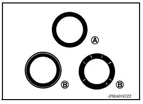
- Apply prussian blue (or white lead) onto contacting surface of valve seat to check the condition of the valve contact on the surface.
- Check if the contact area band is continuous all around the circumference.
(A) : OK
- If not, grind to adjust valve fitting and check again. If the contacting surface still has “NG” conditions (B) even after the recheck, replace valve seat. Refer to EM-74, "Disassembly and Assembly".
VALVE SPRING SQUARENESS
- Set a try square (A) along the side of valve spring and rotate spring. Measure the maximum clearance between the top of spring and try square.
(B) : Contact
Limit : Refer to EM-121, "Cylinder Head".
VALVE SPRING DIMENSIONS AND VALVE SPRING PRESSURE LOAD
- Check valve spring pressure with valve spring seat installed at the specified spring height.
CAUTION:
Do not remove valve spring seat from valve spring.
Standard : Refer to EM-121, "Cylinder Head".
- If the installation load or load with valve open is out of the standard, replace valve spring (with valve spring seat).
INSPECTION AFTER INSTALLATION
- Before starting engine, check oil/fluid levels including engine coolant and engine oil. If less than required quantity, fill to the specified level. Refer to MA-11, "Fluids and Lubricants".
- Use procedure below to check for fuel leakage.
- Turn ignition switch “ON” (with engine stopped). With fuel pressure applied to fuel piping, check for fuel leakage at connection points.
- Start engine. With engine speed increased, check again for fuel leakage at connection points.
- Run engine to check for unusual noise and vibration.
NOTE:
If hydraulic pressure inside timing chain tensioner drops after removal and installation, slack in the guide may generate a pounding noise during and just after engine start. However, this is normal. Noise will stop after hydraulic pressure rises.
- Warm up engine thoroughly to check there is no leakage of fuel, exhaust gases, or any oil/fluids including engine oil and engine coolant.
- Bleed air from lines and hoses of applicable lines, such as in cooling system.
- After cooling down engine, again check oil/fluid levels including engine oil and engine coolant. Refill to the specified level, if necessary.
- Summary of the inspection items:
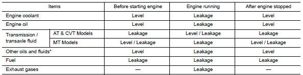
*: Power steering fluid, brake fluid, etc.
 Oil seal
Valve oil seal : Removal and Installation
REMOVAL
Rotate crankshaft, and set piston whose valve oil seal is to be removed
to TDC. This will prevent valve
from dropping into cylinder.
CAUT ...

Other materials:
Precaution for Supplemental Restraint System (SRS) "AIR BAG"
and "SEAT BELT PRE-TENSIONER"
The Supplemental Restraint System such as “AIR BAG” and “SEAT
BELT PRE-TENSIONER”, used along
with a front seat belt, helps to reduce the risk or severity of injury to the
driver and front passenger for certain
types of collision. Information necessary to service the system ...
U1000 CAN Comm circuit
Description
Can (controller area network) is a serial communication line for
real time application. It is an on-vehicle multiplex
communication line with high data communication speed and excellent error
detection ability. Many electronic
control units are equipped onto a vehicle, and each co ...
P062F Eeprom
DTC Logic
DTC DETECTION LOGIC
DTC
CONSULT screen terms
(Trouble diagnosis content)
DTC detection condition
Possible causes
P062F
EEPROM
(Internal Control Module EEPROM
Error)
Flash ROM error is detected when turning ON
the ignition switch.
TC ...
