Nissan Sentra Service Manual: Component parts
Component parts location
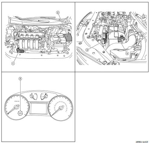
- Generator
- IPDM E/R (view with air inlet duct removed)
- ECM
- Battery current sensor
- Charge warning lamp indicator
Component description
| Component part | Description |
| Generator (IC regulator) | The IC regulator controls the power generation voltage
by the target
power generation voltage based on the received PWM command
signal.
When there is no PWM command signal, the generator performs the normal power generation according to the characteristic of the IC regulator. |
| IPDM E/R | The IPDM E/R converts the received power generation command value into a pulse width modulated (PWM) command signal and sends it to the IC regulator. |
| ECM | The battery current sensor detects the charging/discharging current
of the battery. The ECM judges the battery condition based on
this signal.
The ECM judges whether to request more output via the power generation voltage variable control according to the battery condition. When performing the power generation voltage variable control, the ECM calculates the target power generation voltage according to the battery condition and sends the calculated value as the power generation command value to the IPDM E/R. |
| Battery current sensor | The battery current sensor is located on the negative battery cable terminal. The battery current sensor detects the charging/discharging current of the battery and sends a voltage signal to the ECM according to the current value detected. |
| Combination meter (charge warning lamp) | The IC regulator warning function activates to illuminate the
charge warning lamp if any of the following symptoms occur while
generator is operating:
В·Excessive voltage is produced.
В·No voltage is produced. |

 Charging system
System Diagram
System Description
The generator provides DC voltage to operate the vehicle's electrical system
and to keep the battery charged.
The voltage output is controlled by the IC ...
Other materials:
Bcm branch line circuit
Diagnosis Procedure
1.Check connector
Turn the ignition switch off.
Disconnect the battery cable from the negative terminal.
Check the terminals and connectors of the BCM for damage, bend and loose
connection (unit side and
connector side).
Is the inspection result normal?
YES > ...
Oil pan
Exploded View
O-ring
Oil pan (upper)
Oil level gauge guide
O-ring
Oil level gauge
Oil pump drive chain
Crankshaft sprocket
Oil pump sprocket
Oil pump chain tensioner
Oil pump
Drain plug
Drain plug washer
Oil pan (lower)
Oil filter
Clamp
Water hose
Oil cooler
...
Rearview mirror (if so equipped)
The night position 1 reduces glare from the
headlights of vehicles behind you at night.
Use the day position 2 when driving in daylight
hours.
WARNINGUse the night position only when
necessary,
because it reduces rear view clarity.
...
