Nissan Sentra Service Manual: Can communication circuit
Diagnosis procedure
1.Connector inspection
- Turn the ignition switch off.
- Disconnect the battery cable from the negative terminal.
- Disconnect all the unit connectors on CAN communication system.
- Check terminals and connectors for damage, bend and loose connection.
Is the inspection result normal? Yes >> go to 2.
No >> repair the terminal and connector.
2.Check harness continuity (short circuit)
Check the continuity between the data link connector terminals.
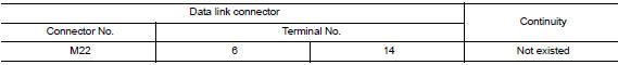
Is the inspection result normal? YES >> GO TO 3.
NO >> Check the harness and repair the root cause.
3.Check harness continuity (short circuit)
Check the continuity between the data link connector and the ground.
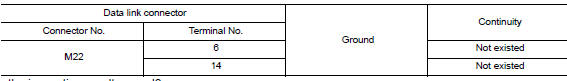
Is the inspection result normal? YES >> GO TO 4.
NO >> Check the harness and repair the root cause.
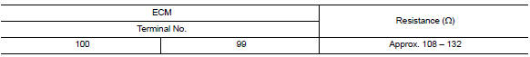
4.Check ecm and bcm termination circuit
- Remove the ecm and the bcm.
- Check the resistance between the ecm terminals.
- Check the resistance between the bcm terminals.
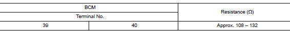
Is the measurement value within the specification? Yes >> go to 5.
No >> replace the ecm and/or the bcm.
5.Check symptom
Connect all the connectors. Check if the symptoms described in the “symptom (results from interview with customer)” are reproduced.
Inspection result
Reproduced>>go to 6.
Non-reproduced>>start the diagnosis again. Follow the trouble diagnosis procedure when past error is detected.
6.Check unit reproduction
Perform the reproduction test as per the following procedure for each unit.
- Turn the ignition switch off
- Disconnect the battery cable from the negative terminal.
- Disconnect one of the unit connectors of can communication system.
Note:
Ecm and bcm have a termination circuit. Check other units first.
- Connect the battery cable to the negative terminal. Check if the symptoms described in the “symptom (results from interview with customer)” are reproduced.
Note:
Although unit-related error symptoms occur, do not confuse them with other symptoms.
Inspection result
Reproduced>>connect the connector. Check other units as per the above procedure.
Non-reproduced>>replace the unit whose connector was disconnected.
 BCM branch line circuit
Diagnosis procedure
1.Check connector
Turn the ignition switch off.
Disconnect the battery cable from the negative terminal.
Check the terminals and connectors of the bcm for damage, bend and ...

Other materials:
Air conditioner system refrigerant and oil recommendations
The air conditioner system in your NISSAN
vehicle must be charged with the refrigerant
HFC-134a (R-134a) and NISSAN A/C
system oil Type S or the exact equivalents.
CAUTION
The use of any other refrigerant or oil will
cause severe damage to the air conditioning
system and will require the repl ...
Air flow charts
The following charts show the button and dial
positions for MAXIMUM AND QUICK heating,
cooling or defrosting. The air recirculation
button should always be in the OFF position
for heating and defrosting.
...
Trunk lid trim
Exploded View
Trunk lid finisher
Front
Removal and Installation
REMOVAL
Remove trunk lid finisher clips (A) and trunk lid finisher.
INSTALLATION
Installation is in the reverse order of removal. ...
