Nissan Sentra Service Manual: BCM branch line circuit
Diagnosis procedure
1.Check connector
- Turn the ignition switch off.
- Disconnect the battery cable from the negative terminal.
- Check the terminals and connectors of the bcm for damage, bend and loose connection (unit side and connector side).
Is the inspection result normal? Yes >> go to 2.
No >> repair the terminal and connector.
2.Check harness for open circuit
- Disconnect the connector of bcm.
- Check the resistance between the bcm harness connector terminals.
- Without intelligent key system
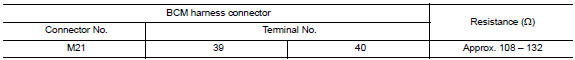
- With Intelligent Key system
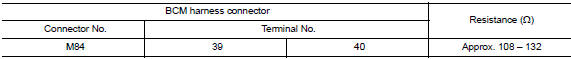
Is the measurement value within the specification? YES >> GO TO 3.
NO >> Repair the BCM branch line.
3.Check power supply and ground circuit
Check the power supply and the ground circuit of the bcm. Refer to the following.
- With intelligent key system: refer to bcs-67, "diagnosis procedure".
- Without intelligent key system: refer to bcs-120, "diagnosis procedure".
Is the inspection result normal? Yes (present error)>>replace the bcm. Refer to the following.
- With Intelligent Key system: Refer to BCS-73, "Removal and Installation".
- Without intelligent key system: refer to bcs-126, "removal and installation".
Yes (past error)>>error was detected in the bcm branch line.
No >> repair the power supply and the ground circuit.
 Hvac branch line circuit
Diagnosis procedure
1.Check connector
Turn the ignition switch off.
Disconnect the battery cable from the negative terminal.
Check the terminals and connectors of the a/c auto amp. For damage ...
 Can communication circuit
Diagnosis procedure
1.Connector inspection
Turn the ignition switch off.
Disconnect the battery cable from the negative terminal.
Disconnect all the unit connectors on CAN communication syste ...
Other materials:
System description
Component parts
POWER DOOR LOCK SYSTEM
POWER DOOR LOCK SYSTEM : Component Parts Location
BCM (view with instrument panel removed)
Front door switch LH
Front door lock actuator LH
Front door lock assembly LH
Front door switch RH
Front door lock actuator RH
Rear door switch RH
...
Basic inspection
Diagnosis and repair workflow
Work flow (with exp-800 ni or gr8-1200 ni)
CHARGING SYSTEM DIAGNOSIS WITH EXP-800 NI OR GR8-1200 NI
To test the charging system, use the following special service tools:
EXP-800 NI Battery and electrical diagnostic analyzer
GR8-1200 NI Multitasking battery and ...
Diagnosis system (BCM)
Common item
Common item : consult function (bcm - common item)
Application item
Consult performs the following functions via can communication with bcm.
System application
Bcm can perform the following functions.
Intelligent key
Intelligent key : consult function (bcm - intelligent ke ...
