Nissan Sentra Service Manual: Can communication circuit
Diagnosis procedure
1.Connector inspection
- Turn the ignition switch OFF.
- Disconnect the battery cable from the negative terminal.
- Disconnect all the unit connectors on can communication system.
- Check terminals and connectors for damage, bend and loose connection.
Is the inspection result normal? Yes >> go to 2.
No >> repair the terminal and connector.
2.Check harness continuity (short circuit)
Check the continuity between the data link connector terminals.
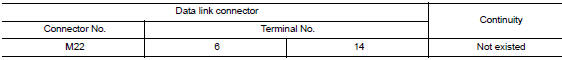
Is the inspection result normal? Yes >> go to 3.
No >> check the harness and repair the root cause.
3.Check harness continuity (short circuit)
Check the continuity between the data link connector and the ground.
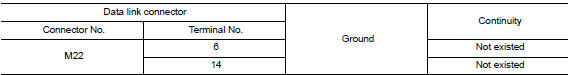
Is the inspection result normal? YES >> GO TO 4.
NO >> Check the harness and repair the root cause.
4.Check ecm and bcm termination circuit
- Remove the ecm and the bcm.
- Check the resistance between the ecm terminals.
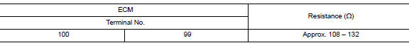
- Check the resistance between the bcm terminals.
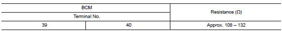
Is the measurement value within the specification? YES >> GO TO 5.
NO >> Replace the ECM and/or the BCM.
5.Check symptom
Connect all the connectors. Check if the symptoms described in the “symptom (results from interview with customer)” are reproduced.
Inspection result
Reproduced>>go to 6.
Non-reproduced>>start the diagnosis again. Follow the trouble diagnosis procedure when past error is detected.
6.Check unit reproduction
Perform the reproduction test as per the following procedure for each unit.
- Turn the ignition switch off.
- Disconnect the battery cable from the negative terminal.
- Disconnect one of the unit connectors of can communication system.
Note:
Ecm and bcm have a termination circuit. Check other units first.
- Connect the battery cable to the negative terminal. Check if the symptoms described in the “symptom (results from interview with customer)” are reproduced.
Note:
Although unit-related error symptoms occur, do not confuse them with other symptoms.
Inspection result
Reproduced>>connect the connector. Check other units as per the above procedure.
Non-reproduced>>replace the unit whose connector was disconnected.
 BCM branch line circuit
Diagnosis procedure
1.Check connector
Turn the ignition switch off.
Disconnect the battery cable from the negative terminal.
Check the terminals and connectors of the bcm for damage, bend and ...
 Can system (type 5)
Dtc/circuit diagnosis ...
Other materials:
CVT Shift selector
Exploded View
Shift selector knob
Lock pin
Knob cover
Position indication panel
Detent switch
Shift lock unit
Park position switch
Shift selector assembly
Shift selector harness assembly
Position bulb
Key interlock rod
With push-button ignition switch
system
Wi ...
Preparation
Special Service Tool
The actual shape of the tools may differ from those illustrated here.
Commercial Service Tool
...
Parking lamp circuit
Description
The ipdm e/r (intelligent power distribution module engine room) controls the
tail lamp relay based on inputs
from the bcm over the can communication lines. When the tail lamp relay is
energized, power flows through
fuse 36, located in the ipdm e/r. Power then flows to the front ...
