Nissan Sentra Service Manual: Brake pedal
Adjustment
BRAKE PEDAL HEIGHT
- Remove instrument lower panel LH. Refer to IP-21, "Removal and Installation".
- Disconnect the harness connectors from the brake pedal position switch (if equipped) and the stop lamp switch.
- Turn the stop lamp switch and brake pedal position switch (if equipped) 45В° counterclockwise.
- Loosen the input rod lock nut (1). Adjust the brake pedal height to the specification.
CAUTION:
- Check the height with the floor trim removed.
- The threaded end of the input rod (2) must project to the inner side (L) of the clevis (3).
Brake pedal height (H1) : Refer to BR-54, "Brake Pedal".
- Tighten the input rod lock nut to specification. Refer to BR-34, "Exploded View".
- Check the brake pedal for smooth operation.
CAUTION:
The stop lamp must turn off when the brake pedal is released.
STOP LAMP SWITCH AND BRAKE PEDAL POSITION SWITCH
- Remove instrument lower panel LH. Refer to IP-21, "Removal and Installation".
- Disconnect the harness connectors from the brake pedal position switch (if equipped) and the stop lamp switch.
- Turn the stop lamp switch and brake pedal position switch (if equipped) 45В° counterclockwise.
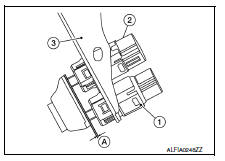
- With the threaded ends of the stop lamp switch (2) and brake
pedal position switch (if equipped) (1) contacting the pedal
bracket (3), turn the switches 45В° clockwise to lock in place.
Check that both the stop lamp switch (2) and brake pedal position switch (if equipped) (1) contact ends to brake pedal bracket (3) clearance (A) are within specification.
- CAUTION:
- Make sure that the clearance (A) between the brake pedal bracket (3), stop lamp switch (2) and the brake pedal position switch (1) contact ends are within specification.
- The stop lamp must turn off when the brake pedal is released.
Clearance (A) : Refer to BR-54, "Brake Pedal".

 Brake fluid
Drain and Refill
CAUTION:
Do not spill or splash brake fluid on painted surfaces. Brake
fluid may damage paint. If brake fluid is
splashed on painted areas, wash it away with water immediate ...
Other materials:
Engine assembly M/T
M/T : Exploded View
Washer
Upper torque rod (RH)
Engine mounting insulator (RH)
Rear torque rod bracket
Rear torque rod
Engine mounting bracket (LH)
Engine mounting frame support (LH)
Engine mounting insulator (LH)
CAUTION:
Check that the stud bolt (*2) is tight at the spe ...
P2004 Intake manifold runner control valve
DTC Logic
DTC DETECTION LOGIC
DTC No.
CONSULT screen terms
(Trouble diagnosis content)
DTC detecting condition
Possible cause
P2004
TUMBLE CONT/V
(Intake manifold runner control
stuck open bank 1)
The target angle of intake manifold runner
control valve c ...
Intermittent Incident
DESCRIPTION
Sometimes the symptom is not present when the vehicle is brought in for
service. If possible, re-create the
conditions present at the time of the incident. Doing so may help avoid a No
Trouble Found Diagnosis. The fol-
lowing section illustrates ways to simulate the conditions/env ...
