Nissan Sentra Service Manual: B terminal circuit
Description
Terminal “B” is constantly supplied with battery power.
Diagnosis Procedure
Regarding Wiring Diagram information, refer to STR-10, "Wiring Diagram" (with Intelligent Key system) or STR-15, "Wiring Diagram" (without Intelligent Key system).
CAUTION:
Perform diagnosis under the condition that the engine cannot start by the following procedure.
- Remove fuel pump fuse.
- Crank or start the engine (where possible) until the fuel pressure is released.
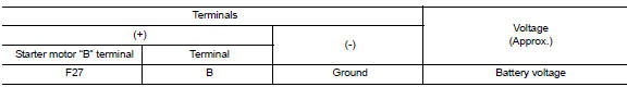
1.CHECK “B” TERMINAL CIRCUIT
- Turn ignition switch OFF
- Check that starter motor B” terminal connection is clean and tight.
- Check voltage between starter motor connector F27 and ground.
Is the inspection result normal? YES >> GO TO 2.
NO >> Check harness between battery and starter motor for open circuit.
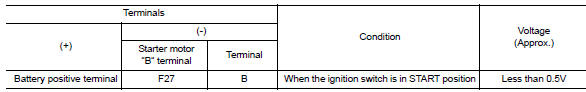
2.CHECK BATTERY CABLE CONNECTION STATUS (VOLTAGE DROP TEST)
- Shift selector lever to P (Park) or N (Neutral) position (CVT Models) or the clutch pedal is depressed (M/T Models).
- Check voltage between battery positive terminal and starter motor B terminal.
Is the inspection result normal? YES >> GO TO 3.
NO >> Check harness between the battery and starter motor for continuity.
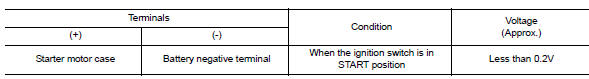
3.CHECK GROUND CIRCUIT STATUS (VOLTAGE DROP TEST)
- Shift selector lever to P (Pack) or N (Neutral) position (CVT Models) or the clutch pedal is depressed (M/T Models).
- Check voltage between starter motor case and battery negative terminal.
Is the inspection result normal? YES >> “B” terminal circuit is OK. Further inspection is necessary. Refer to STR-20, "Work Flow (With GR8-1200 NI)" or STR-24, "Work Flow (Without GR8-1200 NI)".
NO >> Check the starter motor case to engine mounting for high resistance.

 S connector circuit
Description
The starter motor magnetic switch is supplied with power when the ignition
switch is turned to the START position
while the selector lever is in the P (Park) or N (Neutral) position (C ...
Other materials:
ASCD Indicator
Component Function Check
1.CHECK ASCD INDICATOR FUNCTION
Check ASCD indicator under the following conditions.
ASCD INDICATOR
CONDITION
SPECIFICATION
CRUISE LAMP
Ignition switch: ON
MAIN switch: Pressed at the 1st time →
at the 2nd ti ...
Fog light switch (if so equipped)
To turn the fog lights on, turn the headlight switch
to the position, then turn the
fog light
switch to the position.
If the headlight switch is in the AUTO position
and the fog light switch is moved to the ON
position, both the fog lights and the headlights
(including all other ...
Emission control information label
The emission control information label is attached
to the underside of the hood as shown.
Tire and loading information label
The cold tire pressure is shown on the Tire and
Loading Information label. The label is located as
shown.
Air conditioner specification label
The air condit ...
