Nissan Sentra Service Manual: S connector circuit
Description
The starter motor magnetic switch is supplied with power when the ignition switch is turned to the START position while the selector lever is in the P (Park) or N (Neutral) position (CVT Models) or the clutch pedal is depressed (M/T Models).
Diagnosis Procedure
Regarding Wiring Diagram information, refer to STR-10, "Wiring Diagram" (with Intellignet Key system) or STR-15, "Wiring Diagram" (without Intelligent Key system).
CAUTION:
Perform diagnosis under the condition that engine cannot start by the following procedure.
- Remove fuel pump fuse.
- Crank or start the engine (where possible) until the fuel pressure is released.
1.CHECK “S” CONNECTOR CIRCUIT
- Turn ignition switch OFF.
- Disconnect starter motor connector.
- Shift selector lever to “P” (Park) or “N” (Neutral) position (CVT Models) or the clutch pedal is depressed (M/T Models).
- Check voltage between starter motor harness connector F28 and ground.
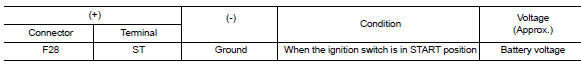
Is the inspection result normal? YES >> “S” circuit is OK. Further inspection is necessary. Refer to STR-20, "Work Flow (With GR8-1200 NI)" or STR-24, "Work Flow (Without GR8-1200 NI)".
NO >> GO TO 2.
2.CHECK HARNESS CONTINUITY (OPEN CIRCUIT)
- Disconnect IPDM E/R connector.
- Check continuity between starter motor harness connector F28 and the IPDM E/R harness connector E44.
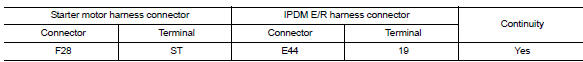
Is the inspection result normal? YES >> Further inspection is necessary. Refer to STR-20, "Work Flow (With GR8-1200 NI)" or STR-24, "Work Flow (Without GR8-1200 NI)".
NO >> Repair or replace the harness or connectors.
 B terminal circuit
Description
Terminal “B” is constantly supplied with battery power.
Diagnosis Procedure
Regarding Wiring Diagram information, refer to STR-10, "Wiring Diagram" (with
Intellig ...
 Symptom diagnosis
Starting system
Symptom table
Symptom
Reference
No normal cranking
Refer to STR-20, "Work Flow (With GR8-1200 NI)" or
STR-24, "Work Flow (Without GR8-1200 NI ...
Other materials:
Diagnosis and repair work flow
Work flow
OVERALL SEQUENCE
DETAILED FLOW
1.INTERVIEW THE CUSTOMER FOR THE SYMPTOM
Interview the customer for the symptom (the condition and the environment
when the incident/malfunction
occurs).
>> GO TO 2.
2.CHECK SYMPTOM
Check the symptom from the customer information.
> ...
Fuel (Regular Unleaded Gasoline Recommended)
Use unleaded regular gasoline with an octane rating of at least 87 AKI
(Anti-Knock Index) number (Research
octane number 91). E-85 fuel (85% fuel ethanol, 15% unleaded gasoline) may only
be used in vehicles specifically
designed for E-85 fuel (i.e. Flexible Fuel Vehicle - FFV models).
CAUTION ...
CD care and cleaning
Handle a CD by its edges. Do not bend the
disc. Never touch the surface of the disc.
Always place the discs in the storage case
when they are not being used.
To clean a disc, wipe the surface from the
center to the outer edge using a clean, soft
cloth. Do not wipe the disc using ...
