Nissan Sentra Service Manual: B0001, B0002 Driver airbag module
Description
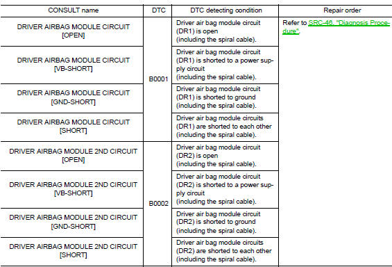
DTC B0001, B0002 DRIVER AIRBAG MODULE
The driver air bag module is dual stage and is wired to the air bag diagnosis sensor unit through the spiral cable. The air bag diagnosis sensor unit will monitor for opens and shorts in detected lines to the driver air bag module including the spiral cable.
PART LOCATION
Refer to SRC-5, "Component Parts Location".
DTC Logic
DTC DETECTION LOGIC
With CONSULT
DTC CONFIRMATION PROCEDURE (With CONSULT)
1.CHECK SELF-DIAG RESULT
- Turn ignition switch ON.
- Check for DTC using CONSULT.
Is the DTC detected? YES (Current DTC)>>Refer to SRC-46, "Diagnosis Procedure".
YES (Past DTC)>>GO TO 2.
NO >> Inspection End.
2.ERASE SELF-DIAG RESULT
Erase the DTC using CONSULT.
Can the DTC be erased? YES >> Inspection End.
NO >> Refer to SRC-46, "Diagnosis Procedure".
DTC CONFIRMATION PROCEDURE (Without CONSULT)
1.CHECK SELF-DIAG RESULT
- Turn ignition switch ON.
- Check the air bag warning lamp status. Refer to SRC-17, "Trouble Diagnosis without CONSULT".
NOTE:
SRS will not enter diagnosis mode if no malfunction is detected in user mode
Is the DTC detected? YES >> Refer to SRC-46, "Diagnosis Procedure".
NO >> Inspection End.
Diagnosis Procedure
1.HARNESS CONNECTOR
Visually inspect all applicable harness connectors for the following:
- Visible damage to connector or terminal
- Loose terminal
- Poor connection
NOTE:
All harness connectors should be inspected from the air bag diagnosis sensor unit to the end component (including any in-line connectors).
Is the inspection result normal? YES >> GO TO 2.
NO >> Perform one of the following repairs:
- Visible damage: Replace the harness.
- Loose terminal: Secure the terminal.
- Poor connection: Secure the connection.
2.CONFIRM DTC
- Reconnect all harness connectors.
- Turn ignition switch ON
- Check for DTC using CONSULT.
Is DTC still current? YES >> GO TO 3.
NO >> Refer to GI-39, "Intermittent Incident".
3.WIRING HARNESS
Check the wiring harness for visible damage.
NOTE:
The entire wiring harness should be inspected from the air bag diagnosis sensor unit to the end component (including any in-line connectors).
Is the inspection result normal? YES >> GO TO 4.
NO >> Replace the harness.
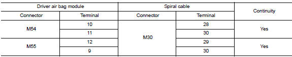
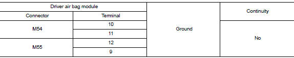
4.Check spiral cable circuit
- Turn ignition switch OFF.
- Disconnect driver air bag module harness connectors and spiral cable harness connector.
- Check continuity between driver air bag module harness connector and spiral cable connector.
- Check continuity between driver air bag module harness connector and ground.
Is the inspection result normal? YES >> GO TO 5.
NO >> Replace the spiral cable. Refer to SR-16, "Removal and Installation".
5.CONFIRM DTC
- Reconnect all harness connectors.
- Turn ignition switch ON.
- Check for DTC using CONSULT.
Is DTC still current? YES >> GO TO 6.
NO >> Refer to GI-39, "Intermittent Incident".
6.AIR BAG DIAGNOSIS SENSOR UNIT
- Replace the air bag diagnosis sensor unit. Refer to SR-28, "Removal and Installation".
- Turn ignition switch ON.
- Check for DTC using CONSULT
Is DTC still current? YES >> GO TO 7.
NO >> Clear DTC. Inspection End.
7.DRIVER AIR BAG MODULE
- Replace the driver air bag module. Refer to SR-12, "Removal and Installation".
- Turn ignition switch ON.
- Check for DTC using CONSULT.
Is DTC still current? YES >> GO TO 8.
NO >> Clear DTC. Inspection End.
8.RELATED HARNESS
Replace the related harness.
>> END
 U1010 Control unit (CAN)
Description
Air bag diagnosis sensor performs self-tests on key ON. If CAN communication
failure within control unit is
detected, DTC is set.
DTC Logic
DTC DETECTION LOGIC
CONSULT name ...
 B0010, B0011 Passenger airbag module
Description
DTC B0010, B0011 PASSENGER AIR BAG MODULE
The passenger air bag module is dual stage and is wired to the air bag
diagnosis sensor unit. The air bag diagnosis
sensor unit will monitor ...
Other materials:
Evaporative emission system
Inspection
EVAP CANISTER
1.CHECK EVAP CANISTER
Block port (B).
Blow air into port (A) and check that it flows freely out of port (C).
Release blocked port (B).
Apply vacuum pressure to port (B) and check that vacuum pressure
exists at the ports (A) and (C).
Block port (A) and (B).
...
Precaution
Precaution for Supplemental Restraint System
(SRS) "AIR BAG" and "SEAT BELT PRE-TENSIONER"
The Supplemental Restraint System such as “AIR BAG” and “SEAT BELT PRE-TENSIONER”,
used along
with a front seat belt, helps to reduce the risk or severity of injury ...
Precautions on seat belt usage
If you are wearing your seat belt properly adjusted
and you are sitting upright and well back in
your seat with both feet on the floor, your chances
of being injured or killed in an accident and/or the
severity of injury may be greatly reduced.
NISSAN strongly encourages you and all of yo ...
