Nissan Sentra B18 (2020-2025) Service Manual: Ventilation System :: Removal and Installation
Ducts and Grilles. Exploded View - With Rear Ducts
Exploded View - With Rear Ducts
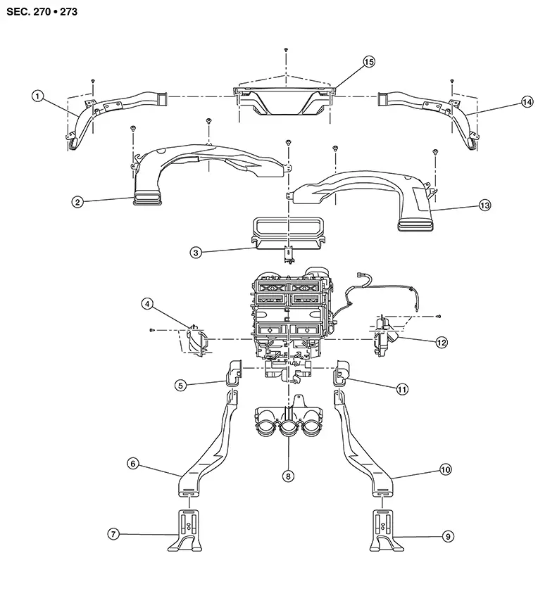
|
1. |
Side defroster duct (LH) |
2. |
Side ventilator duct (LH) |
3. |
Adapter duct |
|
4. |
Front floor duct (LH) |
5. |
Rear floor connecting duct (LH) |
6. |
Rear floor duct (LH) |
|
7. |
Rear floor duct nozzle (LH) |
8. |
Center ventilator duct |
9. |
Rear floor duct nozzle (RH) |
|
10. |
Rear floor duct (RH) |
11. |
Rear floor connecting duct (RH) |
12. |
Front floor duct (RH) |
|
13. |
Side ventilator duct (RH) |
14. |
Side defroster duct (RH) |
15. |
Defroster nozzle |
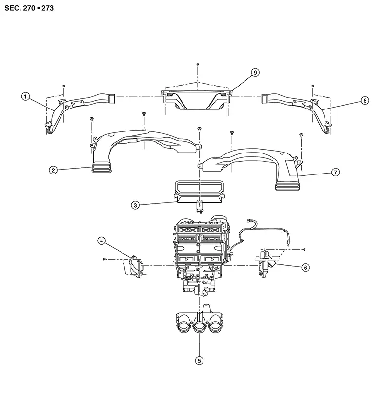
Exploded View - Without Rear Ducts
Exploded View - Without Rear Ducts
|
1. |
Side defroster duct (LH) |
2. |
Side Ventilator duct (LH) |
3. |
Adapter duct |
|
4. |
Front floor duct (LH) |
5. |
Center ventilator duct |
6. |
Front floor duct (RH) |
|
7. |
Side ventilator duct (RH) |
8. |
Side defroster duct (RH) |
9. |
Defroster nozzle |
Defroster Nozzle
Removal and Installation
Removal and Installation
REMOVAL
Remove instrument panel assembly. Refer to Removal and Installation.
Remove
defroster nozzle screws (A), and remove defroster nozzle. 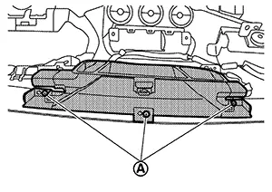
INSTALLATION
Installation is in the reverse order of removal.
Adapter Duct
Removal and Installation
Removal and Installation
REMOVAL
Remove side ventilator duct (LH/RH). Refer to Removal and Installation.
Using a
suitable tool, release pawls and remove adapter duct. 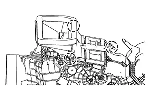
|
|
: Pawl |

INSTALLATION
Installation is in the reverse order of removal.
Side Defroster Duct
Removal and Installation
Removal and Installation
REMOVAL
Remove the instrument panel assembly. Refer to Removal and Installation.
Remove the screws and the side defroster duct. Refer to Exploded View (with rear ducts) or Exploded View (without rear ducts).
INSTALLATION
Installation is in the reverse order of removal.
Side Ventilator Duct
Removal and Installation
Removal and Installation
REMOVAL
Remove the instrument panel assembly. Refer to Removal and Installation.
Remove the side ventilator duct screws. Refer to Exploded View (with rear ducts) or Exploded View (without rear ducts).
Release the side ventilator duct from the defroster duct and remove side ventilator duct (LH/RH).
INSTALLATION
Installation is in the reverse order of removal.
Front Foot Duct
Removal and Installation
Removal and Installation
FRONT FOOT DUCT LH
Removal
Remove left knee air bag module. Refer to Removal and Installation.
Remove instrument finisher C. Refer to Removal and Installation.
Remove
screws (A). 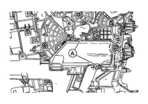
|
|
: Pawl |
Using a suitable tool, release pawl and remove front foot duct LH.
Installation
Installation is in the reverse order of removal.
FRONT FOOT DUCT RH
Removal
Remove the heating and cooling unit assembly. Refer to Removal and Installation.
Remove
screws (A) and release harness retainer (B). 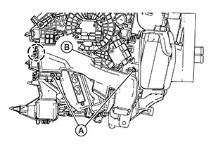
|
|
: Pawl |
Using a suitable tool, release pawl and remove front foot duct RH.
Installation
Installation is in the reverse order of removal.
Rear Floor Duct
Removal and Installation - Rear Floor Connecting Duct
Removal and Installation - Rear Floor Connecting Duct
REMOVAL
Remove center console side finisher (LH/RH). Refer to Exploded View.
Using
suitable tool, release pawls and remove rear floor connecting duct
(LH/RH). 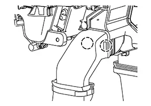
|
|
: Pawl |
INSTALLATION
Installation is in the reverse order of removal.
Removal and Installation - Rear Floor Duct
Removal and Installation - Rear Floor Duct
REMOVAL
Remove rear floor nozzle. Refer to Removal and Installation — Rear Floor Duct Nozzle.
Remove rear floor duct.
INSTALLATION
Installation is in the reverse order of removal.
Removal and Installation - Rear Floor Duct Nozzle
Removal and Installation - Rear Floor Duct Nozzle
REMOVAL
Remove front seat assembly. Refer to Removal and Installation — Seat Assembly (Driver Side) or Removal and Installation — Seat Assembly (Passenger Side).
Remove floor trim. Refer to Removal and Assembly.
Remove front floor spacer (LH/RH). Refer to Exploded View.
Remove rear foot duct (LH/RH).
INSTALLATION
Installation is in the reverse order of removal.
Exploded View
Exploded View
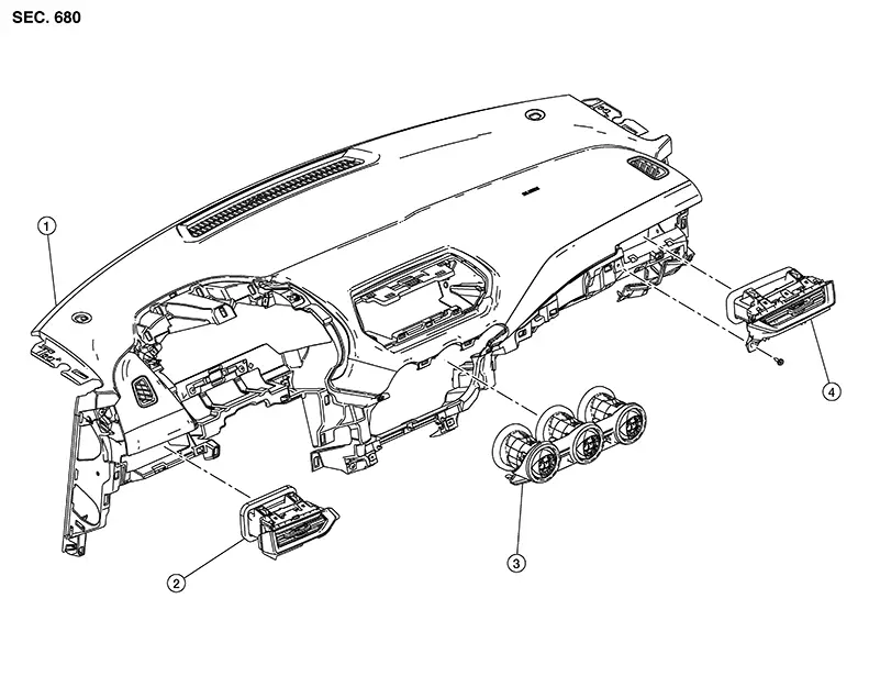
|
1. |
Instrument panel assembly |
2. |
Side ventilator grille (LH) |
3. |
Center ventilator grille |
|
4. |
Side ventilator grille (RH) |
Center Ventilator Grille
Removal and Installation
Removal and Installation
REMOVAL
Remove instrument finisher B. Refer to Removal and Installation.
Using a
suitable tool, release center ventilator grille pawls. 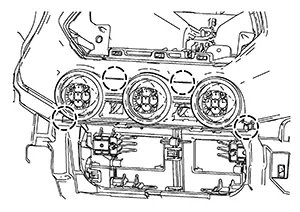
|
|
: Pawl |
Disconnect harness connectors from center ventilator grille and remove center ventilator grille.
Remove hazard switch and passenger air bag off indicator from center ventilator grille (if necessary).
INSTALLATION
Installation is in the reverse order of removal.
Side Ventilator Grille
Removal and Installation
Removal and Installation
SIDE VENTILATOR GRILLE LH
REMOVAL
Remove instrument lower panel LH. Refer to Removal and Installation.
Using a
suitable tool, release pawls and remove side ventilator grille
LH. 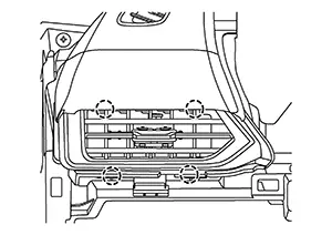
|
|
: Pawl |
INSTALLATION
Installation is in the reverse order of removal.
SIDE VENTILATOR GRILLE RH
REMOVAL
Remove instrument finisher C. Refer to Removal and Installation.
Remove side
ventilator grille screw (A). 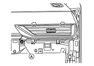
|
|
: Pawl |
Using a suitable tool, release pawls and remove the side ventilator grille RH.
INSTALLATION
Installation is in the reverse order of removal.
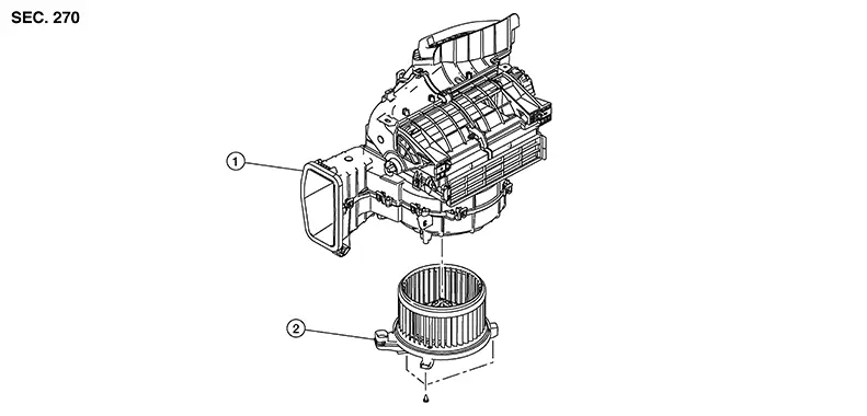
Blower Motor. Exploded View
Exploded View
|
1. |
Blower unit |
2. |
Blower motor |
Removal and Installation
Removal and Installation
REMOVAL
Remove the knee air bag module (RH). Refer to Removal and Installation.
Disconnect harness connector (A)
and remove screws (B). 
Remove blower motor.
INSTALLATION
Installation is in the reverse order of removal.
Other materials:
Basic Inspection
Diagnosis and Repair Workflow
Work Flow
Work Flow
OVERALL SEQUENCE
DETAILED FLOW
GET INFORMATION FOR SYMPTOM
Get detailed information from the customer about
the symptom (the condition and the environment when the
incident/ma ...
C1f4f-82 Bcm Can Circuit 1
Dtc Description
DTC Description
DTC DETECTION LOGIC
DTC
CONSULT screen terms
(Trouble diagnosis
content)
DTC detection
conditi ...
Power Supply, Ground & Circuit Elements. Basic Inspection
Battery
How to Handle Battery
How to Handle Battery
CAUTION:
If it becomes necessary to start the engine with
a booster battery and jumper cables, use a 12-volt booster
battery.
After connecting battery cables, ensure that they
...