Nissan Sentra Service Manual: Unit disassembly and assembly
Front coil spring and strut
Exploded View
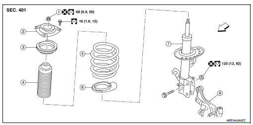
- Piston rod lock nut
- Strut mount insulator
- Strut mount bearing
- Bound bumper
- Coil spring
- Lower rubber seat
- Strut
- Steering knuckle
 Front
Front
Disassembly and Assembly
DISASSEMBLY
CAUTION:
Do not damage the piston rod when removing components from the front coil spring and strut.
- Install Tool (A) to the front coil spring and strut.
CAUTION:
When installing Tool (A), wrap a shop cloth around the front coil spring and strut to protect the parts from damage.
Tool number : ST35652000 ( — )
- Secure Tool (A) in a vise.
- Slightly loosen the piston rod lock nut.
WARNING:
Do not remove the piston rod lock nut completely. If the piston rod lock nut is removed completely, the coil spring can jump out and may cause serious damage or injury.
- Compress the coil spring using a suitable tool (A).
WARNING:
Make sure that the pawls of the suitable tool are firmly hooked on the coil spring. The suitable tool must be tightened alternately so as to not tilt the coil spring.
- Make sure the coil spring is free between the strut mount insulator and the lower rubber seat.
- Hold the piston rod and remove the piston rod lock nut.
- Remove the strut mount insulator, the strut mount bearing, and the bound bumper from the strut.
- Gradually release the suitable tool and remove the coil spring.
CAUTION:
Release the suitable tool while making sure the position of the suitable tool on the coil spring does not move.
- Remove the lower rubber seat.
- Inspect the components. Refer to FSU-21, "Inspection".
ASSEMBLY
CAUTION:
Do not damage the piston rod when removing components from the front coil spring and strut.
- Install the lower rubber seat to the strut.
- Identify the upper side of the coil spring.
 : Upper side
- Compress the coil spring using a suitable tool.
WARNING:
Make sure that the pawls of the suitable tool are firmly hooked on the coil spring. The suitable tool must be tightened alternately so as to not tilt the coil spring.
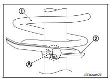
- Align the lower end of the coil spring (1) with the lower rubber seat (2) as shown.
Maximum Gap (A) : 5 mm (0.2 in)
- Apply soapy water to the bound bumper.
CAUTION:
Do not use machine oil.
- Install the bound bumper to the strut.
- Install the strut mount bearing to the coil spring.
CAUTION:
Do not apply oil, such as grease, when installing the strut mount bearing.
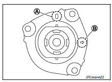
- Install the strut mount insulator to the strut with the identification mark (A) of the strut mount insulator facing toward the front of the vehicle and the arrow (B) facing the outboard side.
NOTE:
The identification mark "0" shows the (RH) strut mount insulator and "1" shows the (LH).
- Secure the piston rod tip so that the piston rod does not turn.
Install the piston rod lock nut and tighten to the specified torque.
CAUTION:
Do not reuse piston rod lock nut.
- Gradually release the suitable tool (A) and remove the suitable tool from the coil spring.
CAUTION:
Release the suitable tool while making sure the position of the suitable tool on the coil spring does not move.
- Remove Tool (A) from the vise.
- Remove Tool (A) from the front coil spring and strut.
- After replacing the strut, always follow the disposal procedure to discard the old strut. Refer to FSU-22, "Disposal".
Inspection
INSPECTION AFTER DISASSEMBLY
Check the following items and replace the parts if necessary.
Strut
- Check the strut for oil leaks, deformation, cracks, or damage.
- Check the piston rod for damage, uneven wear, or distortion.
Strut Mount Insulator and bound bumper
Check the strut mount insulator and the bound bumper for cracks, wear, or damage.
Coil Spring
Check the coil spring for cracks, wear, or damage.
INSPECTION AFTER INSTALLATION
- Check the wheel sensor harness to be sure the connectors are fully seated.
- Check the neutral position of the steering angle sensor. Refer to BRC-54, "Work Procedure".
- Check the wheel alignment. Refer to FSU-6, "Inspection".
Disposal
- Set the strut horizontally with the piston rod fully extended.
- Drill a 2 – 3 mm (0.08 – 0.12 in) hole at the position (

) from top as shown to release gas gradually.
CAUTION:
- Wear eye protection (safety glasses).
- Wear gloves.
- Be careful with metal chips or oil blown out by the compressed gas.
NOTE:
- Drill vertically in this direction (

). - Drill directly to the outer tube avoiding brackets.
- The gas is clear, colorless, odorless, and harmless.
(A) : 20 – 30 mm (0.79 – 1.18 in)
- Position the drilled hole downward and drain oil by moving the piston rod several times.
CAUTION:
Dispose of drained oil according to the law and local regulations.
 Unit removal and installation
Front suspension member
Exploded View
Upper link
Front suspension member
Member stay
Front
Upper link
Front suspension member
Member stay
Front
Removal and Installat ...
 Service data and specifications (SDS)
Wheel Alignment (Unladen*1)
UNITED STATES and CANADA
*1: Fuel, engine coolant, and lubricants are full. Spare tire, jack, hand
tools, and mats are in designated positions.
*2: The difference ...
Other materials:
High-mounted stop lamp
Removal and Installation
HIGH-MOUNTED STOP LAMP - WITH REAR SPOILER
Removal
Remove the rear air spoiler. Refer to EXT-46, "Removal and
Installation".
Remove the screws and the high-mount stop lamp from the rear air
spoiler.
Installation
Installation is in the reverse or ...
Multiport Fuel Injection System or Engine Control System
Before connecting or disconnecting any harness connector for the
multiport fuel injection system or ECM:
Turn ignition switch to –≤–Ç—öOFF–≤–Ç—ú position.
Disconnect negative battery terminal.
Otherwise, there may be damage to ECM.
Before disconnecting pressurized fuel line from ...
Bluetooth® settings
To access and adjust the settings for the
Bluetooth® Hands-Free Phone System:
Press the SETTING button.
Use the TUNE/SCROLL knob to select
“Bluetooth” and then press the ENTER button:
Bluetooth
Select “On” or “Off” to turn the vehicle’s
Bluetooth® system on or ...
