Nissan Sentra B18 (2020-2025) Service Manual: System Description
Component Parts
Eco Mode System
Component Parts Location
Component Parts Location
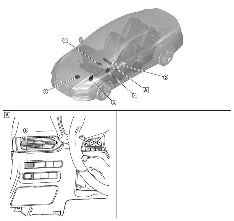
|
A. |
Instrument lower panel LH |
|
No. |
Component |
Function |
|---|---|---|
|
1. |
A/C auto amp. (Auto A/C) |
The A/C auto amp. or A/C amp. receives the ECO mode signal from the BCM via CAN communication. Refer to Component Parts Location (Auto A/C), Component Parts Location (Manual A/C) for detailed component location. |
|
A/C amp. (Manual A/C) |
||
|
2. |
Electric throttle control actuator |
Refer to Component Description for detailed component location. |
|
3. |
ECM (Engine Control Module) |
The ECM receives the ECO mode signal from the BCM via CAN communication. Refer to Component Parts Location for detailed component location. |
|
4. |
BCM (Body Control Module) |
Refer to System Description. |
|
5. |
Combination meter |
The combination meter receives the ECO mode indicator signal via CAN communication from the BCM. Refer to Component Parts Location (Type A) or Component Parts Location (Type B) for detailed component location. |
|
6. |
ECO mode switch |
Refer to ECO Mode Switch. |
Eco Mode Switch
ECO Mode Switch
-
The ECO mode switch is installed to the instrument lower finisher.

-
When the ECO mode indicator lamp on the combination meter is OFF and the ECO mode switch is pressed, the ECO mode is active and the ECO mode indicator lamp is ON.
-
When the ECO mode indicator lamp on the combination meter is ON and the ECO mode switch is pressed, the ECO mode is cancelled and the ECO mode indicator lamp is OFF.
Eco Mode Indicator Lamp
ECO Mode Indicator Lamp
DESIGN/PURPOSE
The ECO mode indicator lamp inform the driver that the vehicle is in ECO mode.

SIGNAL PATH
-
Combination meter receives ECO mode switch signal (ON/OFF) from BCM via CAN communication.
Based on the signal, BCM transmits ECO mode signal to ECM via CAN communication.
-
ECM transmits ECO mode indicator signal to combination meter via CAN communication. Based on the signal, combination meter illuminates ECO mode indicator lamp.
LIGHTING CONDITION
When all of the following conditions are satisfied.
-
Ignition switch: ON
-
The ECO mode switch is pressed when the ECO mode indicator lamp is OFF
SHUTOFF CONDITION
When any of the condition listed below is satisfied.
-
Ignition switch: Other than ON
-
The ECO mode switch is pressed when the ECO mode indicator lamp is ON.
System
Eco Mode Control
System Description
System Description
SYSTEM DIAGRAM
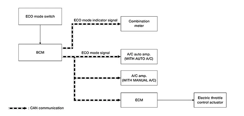
INPUT/OUTPUT SIGNAL CHART
|
Signal name |
Input |
Output |
Description |
|---|---|---|---|
|
ECO mode signal |
|
BCM |
Transmits ECO mode signal to ECM and A/C auto amp meter via CAN communication. |
|
ECO mode indicator signal |
Combination meter (CAN) |
BCM |
Transmits ECO mode indicator signal to combination meter via CAN communication. |
BCM CONTROL
-
BCM receives the ECO mode switch signal (ON/OFF) by hard wire. BCM transmits ECO mode signal to other control unit via CAN communication.
-
BCM transmits ECO mode indicator signal to combination meter via CAN communication. Combination meter illuminates ECO mode indicator lamp according to the signal.
-
For Air Conditioning Control details. Refer to System Description(Auto A/C) or System Description(Manual A/C).

When the ignition switch is placed ON while the ECO mode indicator lamp stays ON, the ECO mode is automatically turned OFF at the next ignition switch ON.
ECM CONTROL
-
ECM receives the ECO mode signal from BCM via CAN communication and improves the fuel economy by controlling the throttle movement to less than usual. (reducing energy consumption by decreasing needless acceleration and deceleration), so that operation of fuel efficiency driving is assisted.
-
ECM transmits ECO mode indicator signal to combination meter via CAN communication. Combination meter illuminates ECO mode indicator lamp according to the signal.
-
For Air Conditioning Control details.
When the ignition switch is placed OFF while the ECO mode indicator lamps stays ON, the ECO mode indicator lamp automatically turns ON at the next ignition switch ON.
A/C AUTO AMP. CONTROL
For details of air conditioning control, Refer to System Description.
A/C AMP. CONTROL
For details of air conditioning control, Refer to System Description.
FAIL-SAFE
If a malfunction occurs in the CAN communication during ECO mode, the ECO mode is kept until ignition off, ECO mode is turned off automatically at the next ignition switch ON.
Warning/indicator/chime List
Warning / Indicator / Chime List
Warning / Indicator / Chime List
|
Name |
Design |
Layout/Function |
|---|---|---|
|
ECO mode indicator lamp |
|
Refer to ECO Mode Indicator Lamp. |

Other materials:
P2b96 Injection Pulse
Dtc Description
DTC Description
DTC DETECTION LOGIC
DTC
CONSULT screen terms
(Trouble diagnosis
content)
DTC detection
condition
...
Door Does Not Lock/unlock with Intelligent Key
Description
Description
All doors do not lock/unlock using Intelligent
Key button.
Note:
Before starting diagnosis check that Nissan Sentra vehicle
condition is as shown in “Conditions of vehicle�, and
check each symptom.
SYMPTOM TABLE (BOTH INTELLIGENT KEYS HAVE
THE ...
Hazard warning flasher switch
Press the hazard warning flasher switch to alert other drivers when you must
stop or park your Nissan Sentra under emergency conditions. When activated, all
turn signal lights will flash simultaneously to increase vehicle visibility and
warn surrounding traffic.
WARNING
If stopping du ...