Nissan Sentra Service Manual: System description
Component parts
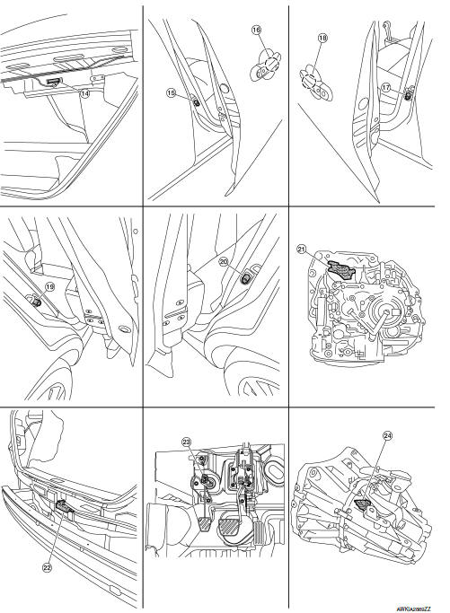
Component parts location
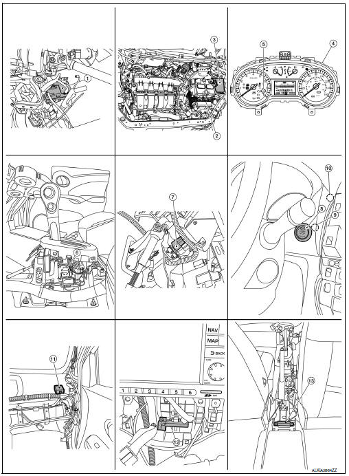
- BCM (view with instrument panel removed)
- ECM
- IPDM E/R
- Combination meter
- Security indicator lamp
- CVT shift selector (park position switch) (view with center console removed)
- Stop lamp switch
- Push button ignition switch
- NATS antenna amp.
- Dongle unit (Canada only)
- Remote keyless entry receiver (view with instrument panel removed)
- Inside key antenna (instrument center)
- Inside key antenna (console) (view with center console removed)
- Inside key antenna (trunk)
- Front door switch RH
- Outside key antenna (passenger side)
- Front door switch LH
- Outside key antenna (driver side)
- Rear door switch RH
- Rear door switch LH
- Transmission range switch (CVT)
- Outside key antenna (rear bumper)
- Clutch interlock switch (M/T)
- Park/neutral position (PNP) switch (neutral switch) (M/T)
Component description
CVT shift selector (park position switch)
Park position switch detects that CVT shift selector is in the P (Park) position and then transmits the signal to BCM and IPDM E/R.
BCM confirms the CVT shift selector position with the following 5 signals:
- P (Park) position signal from CVT shift selector (park position switch)
- P/N position signal from TCM
- P (Park) position signal from IPDM E/R (CAN)
- P/N position signal from IPDM E/R (CAN)
- P/N position signal from TCM (CAN)
IPDM E/R confirms the CVT shift selector position with the following 3 signals:
- P (Park) position signal from CVT shift selector (park position switch)
- P/N position signal from TCM
- P/N position signal from BCM (CAN)
BCM
BCM controls INTELLIGENT KEY SYSTEM (ENGINE START FUNCTION), NISSAN VEHICLE IMMOBILIZER SYSTEM-NATS (NATS), and VEHICLE SECURITY SYSTEM.
BCM performs the ID verification between BCM and Intelligent Key when the Intelligent Key is carried into the detection area of inside key antenna and push-button ignition switch is pressed. If the ID verification result is OK, push-button ignition switch operation is available.
Then, when the power supply position is turned ON, BCM performs ID verification between BCM and ECM. If the ID verification result is OK, ECM can start engine.
ECM
ECM controls the engine.
When power supply position is turned ON, BCM starts communication with ECM and performs the ID verification between BCM and ECM.
If the verification result is OK, the engine can start. If the verification result is invalid, the engine can not start.
IPDM E/R
IPDM E/R has the starter relay and starter control relay inside. Starter relay and starter control relay are used for the engine starting function. IPDM E/R controls these relays while communicating with BCM.
NATS Antenna Amp
The ID verification is performed between BCM and transponder in Intelligent Key via NATS antenna amp.
when Intelligent Key backside is contacted to push-button ignition switch in case that Intelligent Key battery is discharged. If the ID verification result is OK, the operation of starting engine is available.
Combination Meter
Combination meter transmits the vehicle speed signal to BCM via CAN communication.
BCM also receives the vehicle speed signal from ABS actuator and electric unit (control unit) via CAN communication.
BCM compares both signals to detect the vehicle speed.
Door Switch
Door switch detects door open/close condition and then transmits ON/OFF signal to BCM.
Outside Key Antenna
Outside key antenna detects whether Intelligent Key is outside the vehicle and transmits the signal to BCM.
Three outside key antennas are installed in the front outside handle LH, front outside handle RH and rear bumper.
Inside Key Antenna
Inside key antenna detects whether Intelligent Key is inside the vehicle and transmits the signal to BCM.
Three inside key antennas are installed in the instrument center, console and trunk room.
Remote Keyless Entry Receiver
Remote keyless entry receiver receives each button operation signal and electronic key ID signal from Intelligent Key and then transmits the signal to BCM.
Intelligent Key
Each Intelligent Key has an individual electronic ID and transmits the ID signal by request from BCM.
Carrying the Intelligent Key whose ID is registered in BCM, the driver can perform, remote start, door lock/ unlock operation, remote liftgate, panic alarm and push-button ignition switch operation.
Push-button Ignition Switch
Push-button ignition switch detects that push-button is pressed and then transmits the signal to BCM. BCM changes the power supply position with the operation of push-button ignition switch. BCM maintains the power supply position status while push-button is not operated.
Security Indicator Lamp
Security indicator lamp is located on combination meter.
Security indicator lamp blinks when power supply position is any position other than ON to warn that NISSAN VEHICLE IMMOBILIZER SYSTEM-NATS (NATS) is on board.
Starter Relay
Engine starting system functions by controlling both starter relay and starter control relay.
Both relays are integrated in IPDM E/R. Starter relay is controlled by BCM, and starter control relay is controlled by IPDM E/R on request from BCM.
IPDM E/R transmits starter relay and starter control relay status signal to BCM via CAN communication.
Stop Lamp Switch
Stop lamp switch detects that brake pedal is depressed, and then transmits the signal to BCM.
Transmission Range Switch
Transmission range switch is integrated in CVT assembly, and detects the CVT shift selector position.
TCM receives the transmission range switch signal and then transmits the P/N position signal to BCM and IPDM E/R.
BCM confirms the CVT shift selector position with the following 5 signals:
- P (Park) position signal from CVT shift selector (park position switch)
- P/N position signal from TCM
- P (Park) position signal from IPDM E/R (CAN)
- P/N position signal from IPDM E/R (CAN)
- P/N position signal from TCM (CAN)
IPDM E/R confirms the CVT shift selector position with the following 3 signals:
- P (Park) position signal from CVT shift selector (park position switch)
- P/N position signal from TCM
- P/N position signal from BCM (CAN)
Park/neutral position (PNP) switch (neutral switch)
Park/neutral position (PNP) switch detects that shift lever is in the neutral position, and then transmits ON/OFF signal to BCM.
Clutch interlock switch
Clutch interlock switch detects that clutch pedal is depressed, then provides power source to starter control relay and starter relay, and transmits ON/OFF signal to BCM.
System
Intelligent key system/engine start function
Intelligent key system/engine start function : system description
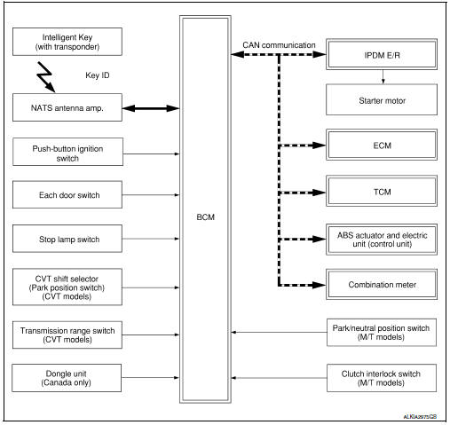
SYSTEM DIAGRAM
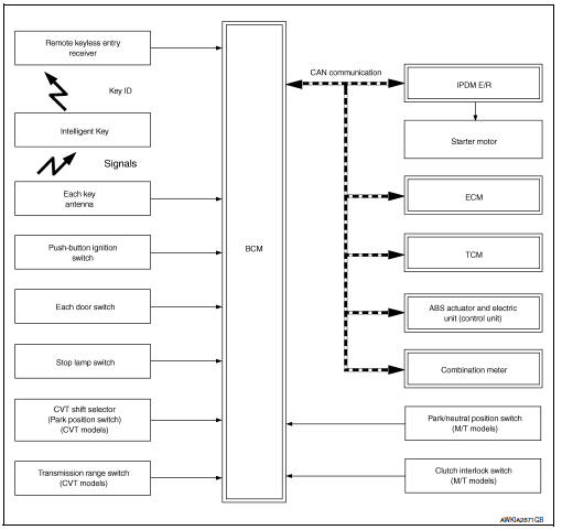
SYSTEM DESCRIPTION
- The engine start function of Intelligent Key system makes it possible to start and stop the engine without using the key, based on the electronic ID verification. The electronic ID verification is performed between BCM and Intelligent Key when the push-button ignition switch is pressed while the Intelligent Key is within the detection area of inside key antenna.
NOTE:
The driver should carry the Intelligent Key at all times.
- Intelligent Key has 2 IDs (Intelligent Key ID and NATS ID). It can perform the door lock/unlock operation and the push-button ignition switch operation when the registered Intelligent Key is carried.
- If the ID is successfully verified, when push-button ignition switch is pressed the engine can be started.
- Up to 4 Intelligent Keys can be registered (Including the standard Intelligent Key) upon request from the customer.
NOTE:
Refer to SEC-14, "NISSAN ANTI-THEFT SYSTEM : System Description" for any functions other than engine start function of Intelligent Key system.
PRECAUTIONS FOR INTELLIGENT KEY SYSTEM
The transponder (the chip for NATS ID verification) is integrated into the Intelligent Key. (For the conventional models, it is integrated into the mechanical key.) Therefore, ID verification cannot be performed by mechanical key only.
In that case, NATS ID verification can be performed when Intelligent Key backside is contacted to push-button ignition switch while brake pedal is depressed. If verification result is OK, engine can be started.
OPERATION WHEN INTELLIGENT KEY IS CARRIED
- When the push-button ignition switch is pressed, the BCM activates the inside key antenna and transmits the request signal to the Intelligent Key.
- The Intelligent Key receives the request signal and transmits the Intelligent Key ID signal to the BCM.
- BCM receives the Intelligent Key ID signal via remote keyless entry receiver and verifies it with the registered ID.
- BCM turns ACC relay ON and transmits the ignition power supply ON signal to IPDM E/R.
- IPDM E/R turns the ignition relay ON and starts the ignition power supply.
- IPDM E/R turns the starter control relay ON for engine starting in advance.
- BCM detects the selector lever position and brake pedal operation condition (CVT models), or clutch pedal operation condition (M/T models).
- BCM transmits the starter request signal to IPDM E/R and turns the starter relay in IPDM E/R ON if BCM judges that the engine start condition* is satisfied.
- Power supply is supplied through the starter relay and the starter control relay to operate the starter motor.
CAUTION:
If a malfunction is detected in the Intelligent Key system, the “KEY” warning lamp on the combination meter illuminates. At that time, the engine cannot be started.
- When BCM receives feedback signal from ECM indicating that the engine is started, the BCM transmits a stop signal to IPDM E/R and stops cranking by turning OFF the starter motor relay. (If engine start is unsuccessful, cranking stops automatically within 5 seconds.)
CAUTION:
When the Intelligent Key is carried outside of the vehicle (inside key antenna detection area) while the power supply is in the ACC or ON position, even if the engine start condition* is satisfied, the engine cannot be started.
*: For the engine start condition, refer to “IGNITION SWITCH POSITION CHANGE TABLE BY PUSH-BUTTON IGNITION SWITCH OPERATION”.
OPERATION RANGE
Engine can be started when Intelligent Key is inside the vehicle. However, sometimes engine may not start when Intelligent Key is on instrument panel or in glove box.
ENGINE START OPERATION WHEN INTELLIGENT KEY IS CONTACTED TO PUSH-BUTTON IGNITION SWITCH
When Intelligent Key battery is discharged, NATS ID verification between transponder in Intelligent Key and BCM is performed when Intelligent Key backside is contacted to push-button ignition switch while brake pedal is depressed. If the verification result is OK, engine can be started.
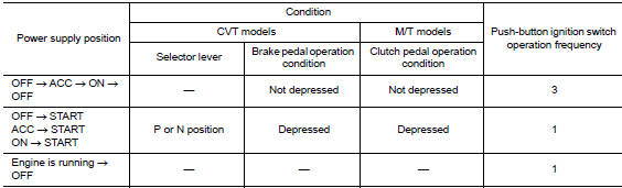
IGNITION SWITCH POSITION CHANGE TABLE BY PUSH-BUTTON IGNITION SWITCH OPERATION
The ignition switch position can be changed by the following operations.
NOTE:
- When an Intelligent Key is within the detection area of inside key antenna or when Intelligent Key backside is contacted to push-button ignition switch, it is equivalent to the operations below.
- When starting the engine, the BCM monitors under the engine start conditions,
CVT models
- Brake pedal operation condition
- Selector lever position
- Vehicle speed
M/T models
- Clutch pedal operation condition
- Vehicle speed
Vehicle speed: less than 4 km/h (2.5 MPH)
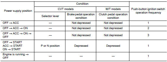
Vehicle speed: 4 km/h (2.5 MPH) or more
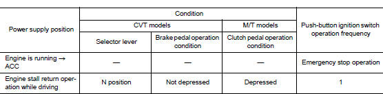
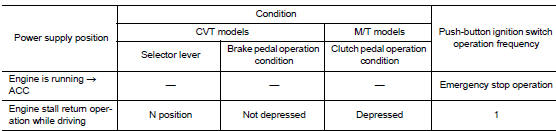
Emergency stop operation
- Press and hold the push-button ignition switch for 2 seconds or more.
- Press the push-button ignition switch 3 times or more within 1.5 seconds.
Nissan anti-theft system
Nissan anti-theft system : system description
SYSTEM DIAGRAM
SYSTEM DESCRIPTION
- The Nissan Anti-Theft System (NATS) prevents the engine from being started by Intelligent Key whose ID is not registered to the vehicle (BCM). It has higher protection against auto theft involving the duplication of mechanical keys.
- The ignition key integrated in the Intelligent Key cannot start the engine. When the Intelligent Key battery is discharged, the NATS ID verification is performed between the transponder integrated with Intelligent Key and BCM via NATS antenna amp. when the Intelligent Key backside is contacted to push-button ignition switch while brake pedal is depressed. If the verification result is OK, the engine start operation can be performed by the push-button ignition switch operation.
- Locate the security indicator lamp and always blinks it when the ignition switch is in any position except ON to warn that the vehicle is equipped with Nissan Anti-Theft System (NATS).
- Up to 4 Intelligent Keys can be registered (including the standard ignition key) upon request from the owner.
- When replacing ECM, BCM or Intelligent Key, the specified procedure (Initialization and registration) using CONSULT is required.
- Possible symptom of NATS malfunction is “Engine can not start”. This symptom also occurs because of other than NATS malfunction, so start the trouble diagnosis according to GI-35, "Work Flow".
- If ECM other than genuine part is installed, the engine cannot be
started.
For ECM replacement procedure, refer to EC-485, "Removal and Installation".
PRECAUTIONS FOR KEY REGISTRATION
- The ID registration is a procedure that erases the current NATS ID once, and then registers a new ID. Therefore before starting the registration operation, collect all registered Intelligent Keys from the customer.
- When registering the Intelligent Key, perform only one procedure to simultaneously register both IDs (NATS ID and Intelligent Key ID).
SECURITY INDICATOR LAMP
- Security indicator lamp warns that the vehicle is equipped with NATS.
- Security indicator lamp always blinks when the ignition switch is in any position other than ON.
NOTE:
Because security indicator lamp is highly efficient, the battery is barely affected.
ENGINE START OPERATION WHEN INTELLIGENT KEY IS CONTACTED TO PUSH-BUTTON IGNITION SWITCH
- When brake pedal is depressed while selector lever is in the P position (CVT models), or selector lever is in the Neutral position (M/T models), the BCM activates NATS antenna amp. that is located behind pushbutton ignition switch.
- When Intelligent Key (transponder built-in) backside is contacted to push-button ignition switch, BCM starts NATS ID verification between BCM and Intelligent Key (transponder built-in) via NATS antenna amp.
- When NATS ID verification result is OK, buzzer in combination meter sounds and BCM transmits the result to ECM.
- BCM turns ACC relay ON and transmits ignition power supply ON signal to IPDM E/R.
- IPDM E/R turns the ignition relay ON and starts the ignition power supply.
- IPDM E/R turns the starter control relay ON for engine starting in advance.
- BCM detects that the selector lever position and brake pedal operation condition (CVT models), or clutch pedal operation condition (M/T models).
- BCM transmits starter request signal to IPDM E/R and turns the starter relay in IPDM E/R ON if BCM judges that the engine start condition* is satisfied.
- Power supply is supplied through the starter relay and the starter control relay to operate the starter motor.
- When BCM receives feedback signal from ECM indicating that the engine is started, BCM transmits a stop signal to IPDM E/R and stops cranking by turning off the starter motor relay. (If engine start is unsuccessful, cranking stops automatically within 5 seconds.)
*: For the engine start condition, refer to “IGNITION SWITCH POSITION CHANGE TABLE BY PUSH-BUTTON IGNITION SWITCH OPERATION” below.
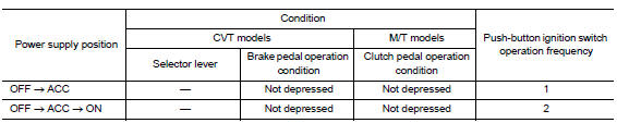
IGNITION SWITCH POSITION CHANGE TABLE BY PUSH-BUTTON IGNITION SWITCH OPERATION
The ignition switch position can be changed by the following operations.
NOTE:
- When an Intelligent Key is within the detection area of inside key antenna or when Intelligent Key backside is contacted to push-button ignition switch, it is equivalent to the operations below.
- When starting the engine, the BCM monitors under the engine start conditions,
CVT models
- Brake pedal operation condition
- Selector lever position
- Vehicle speed
M/T models
- Clutch pedal operation condition
- Vehicle speed
Vehicle speed: less than 4 km/h (2.5 MPH)
Vehicle speed: 4 km/h (2.5 MPH) or more
Emergency stop operation
- Press and hold the push-button ignition switch for 2 seconds or more.
- Press the push-button ignition switch 3 times or more within 1.5 seconds.
Vehicle security system
Vehicle security system : system description
- The vehicle security system has two alarm functions (theft warning alarm and panic alarm) and reduces the possibility of a theft or mischief by activating horns and headlamps intermittently
- The panic alarm does not start when the theft warning alarm is
activating and the panic alarm stops when
the theft warning alarm is activated.
The priority of the functions are as per the following.

THEFT WARNING ALARM
- The theft warning alarm function activates horns and headlamps intermittently when BCM detects that any door is opened by unauthorized means while the system is in the ARMED state
- Security indicator lamp on combination meter always blinks when power supply position is any position other than ON. Security indicator lamp blinking warns that the vehicle is equipped with a vehicle security system.
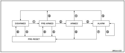
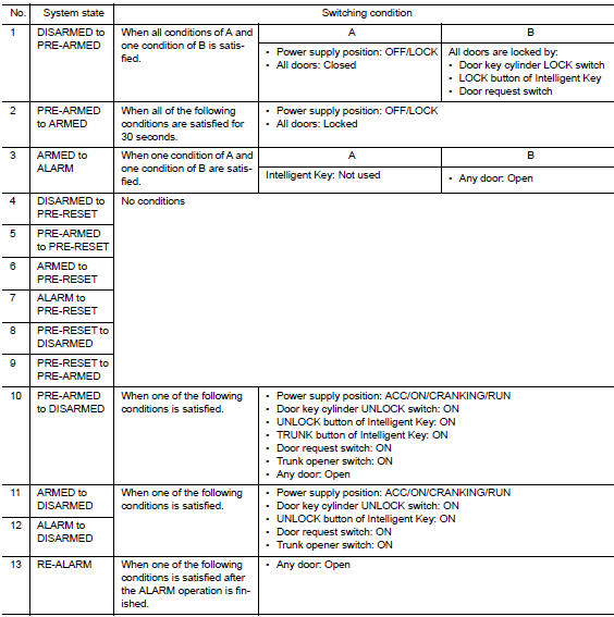
Operation Flow
NOTE:
- BCM ignores the door key cylinder UNLOCK switch signal input for 1 second after the door key cylinder LOCK switch signal input.
- To lock/unlock all doors by operating remote controller button of Intelligent Key or door request switch, Intelligent Key must be within the detection area of outside key antenna. For details, refer to SEC-11, "INTELLIGENT KEY SYSTEM/ENGINE START FUNCTION : System Description".
- To open trunk by operating trunk opener switch, Intelligent Key must be within the detection area of outside key antenna. For details, refer to SEC-11, "INTELLIGENT KEY SYSTEM/ENGINE START FUNCTION : System Description".
DISARMED Phase
The vehicle security system is not set in the DISARMED phase. The vehicle security system stays in this phase while any door is open because it is assumed that the owner is inside or nearby the vehicle. Security indicator lamp blinks every 2.4 seconds.
When the vehicle security system is reset, each phase switches to the DISARMED phase directly.
PRE-ARMED Phase
The PRE-ARMED phase is the transient state between the DISARMED phase and the ARMED phase. This phase is maintained for 30 seconds so that the owner can reset the setting due to a mis-operation. This phase switches to the ARMED phase when vehicle conditions are not changed for 30 seconds. Security indicator lamp illuminates while being in this phase.
To reset the PRE-ARMED phase, refer to the switching condition of No. 10 in the table above.
ARMED Phase
The vehicle security system is set and BCM monitors all necessary inputs. If any door is opened without using Intelligent Key, vehicle security system switches to the ALARM phase. Security indicator lamp blinks every 2.4 seconds.
To reset the ARMED phase, refer to the switching condition of No. 11 in the table above.
ALARM Phase
BCM transmits “Theft Warning Horn Request” signal and “High Beam Request” signal intermittently to IPDM E/R via CAN communication. In this phase, horns and headlamps are activated intermittently for approximately 50 seconds to warn that the vehicle is accessed by unauthorized means. ON/OFF timing of horns and headlamps are synchronized. After 50 seconds, the vehicle security system returns to the ARMED phase. At this time, if BCM still detects unauthorized access to the vehicle, the system is switched to the ALARM phase again. This RE-ALARM operation is carried out a maximum of 2 times.
To cancel the ALARM operation, refer to the switching condition of No. 12 in the table above.
NOTE:
If a battery terminal is disconnected during the ALARM phase, theft warning alarm stops. But when the battery terminal is reconnected, theft warning alarm is activated again.
PANIC ALARM
- The panic alarm function activates horns and headlamps intermittently when the owner presses the PANIC ALARM button of Intelligent Key outside the vehicle while the power supply position is OFF or LOCK.
- When BCM receives panic alarm signal from Intelligent Key, BCM transmits “Theft Warning Horn Request” signal and “High Beam Request” signal intermittently to IPDM E/R via CAN communication. To prevent the activation due to mis-operation of Intelligent Key by owner, the panic alarm function is activated when BCM receives the signal for 0.4 - 0.6 seconds.
- Panic alarm operation is maintained for 25 seconds.
- Panic alarm operation is cancelled when BCM receives one of the following signals:
- LOCK button of Intelligent Key: ON
- UNLOCK button of Intelligent Key: ON
- PANIC ALARM button of Intelligent Key: Long pressed
- Any door request switch: ON
 Precaution
Precaution for supplemental restraint system (SRS) "air bag" and "seat
belt pre-tensioner"
The supplemental restraint system such as “air bag” and “seat belt pre- ...
 Diagnosis system (BCM)
Common item
Common item : consult function (bcm - common item)
APPLICATION ITEM
CONSULT performs the following functions via CAN communication with BCM.
SYSTEM APPLICATION
BCM can perform the ...
Other materials:
B00A0 OCS System
Description
DTC B00A0 OCCUPANT CLASSIFICATION SYSTEM (OCS)
The OCS control unit is wired to the air bag diagnosis sensor unit. The air
bag diagnosis sensor unit will monitor
the OCS for failures and interruptions in communication between the OCS control
unit and the air bag
diagnosis sensor ...
Operating range
The Intelligent Key functions can only be used
when the Intelligent Key is within the specified
operating range.
When the Intelligent Key battery is almost discharged
or strong radio waves are present near
the operating location, the Intelligent Key system’s
operating range becomes nar ...
Preparation
Special service tools
The actual shape of the tools may differ from those illustrated here.
Commercial service tools
Clip list
Descriptions for Clips
Replace any clips which are damaged during removal or installation.
...
