Nissan Sentra B18 (2020-2025) Service Manual: System
Relay Control System
System Description
System Description
SYSTEM DIAGRAM
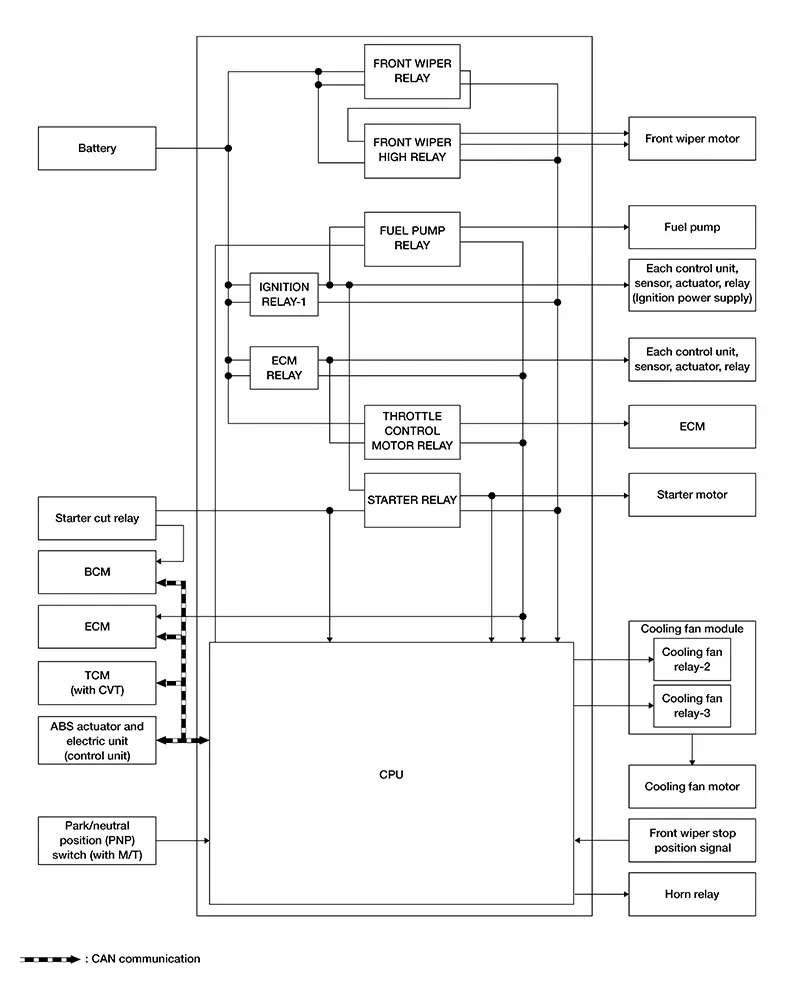
DESCRIPTION
The IPDM E/R activates the internal control circuit to perform relay ON-OFF control according to the input signals from various sensors and the request signals received from control units via CAN communication.
Note:
IPDM E/R integrated relays cannot be removed.
|
Control relay |
Input/output |
Transmit unit |
Control part |
Reference |
|---|---|---|---|---|
|
Front wiper request signal |
BCM (CAN) |
Front wiper motor |
System Description |
|
Front wiper stop position signal |
Front wiper motor |
|||
|
Starter relay |
Ignition switch ON signal |
BCM (CAN) |
Starter motor |
System Description |
|
Cranking enable (ECM) signal |
ECM (CAN) |
|||
|
Cranking enable (TCM) signal1 |
TCM (CAN)1 |
|||
|
Clutch switch signal2 |
BCM (CAN) |
|||
|
Neutral position signal2 |
Park/neutral position (PNP) switch2 |
|||
|
Ignition relay-1 |
Ignition switch ON signal |
BCM (CAN) |
Each control unit, sensor, actuator, relay (ignition power supply) |
— |
|
Nissan Sentra Vehicle speed signal |
ABS actuator and electric unit (control unit) (CAN) |
1: With CVT
2: With M/T
Note:
ECM controls the following relays:
-
ECM relay
-
Fuel pump relay
-
Throttle control motor relay
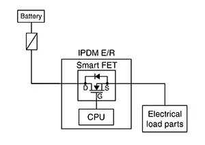
Smart Field-Effect Transistor (fet)
System Description
System Description
A Smart Field-Effect Transistor (FET) is a transistor used to monitor and control current flow on module outputs. The IPDM E/R uses a Smart FET protection strategy to prevent module damage in the event of excessive current flow. The Smart FET protection strategy monitors its outputs for excessive current, and when a fault occurs, shuts down the output and records a DTC.
COMPONENT FUNCTION WITHIN SYSTEM
-
The Smart FET turns the each lamps ON according to the request from the BCM.
-
The Smart FET turns the A/C compressor (magnetic clutch) ON according to the request from the ECM.
INDIVIDUAL COMPONENT FUNCTION
The Smart FET supplies power supply voltage to the each lamp and the A/C compressor (magnetic clutch).
COMPONENT OPERATION
The Smart FET, that uses MOS field effect transistor, is adopted for each lamp and the A/C compressor (magnetic clutch) control.
 Note:
Note:
A MOS field effect transistor is a transistor in which the gate is composed of a metal-oxide-semiconductor (MOS). Field effect transistor is controlled by voltage, while ordinary transistor is controlled by current. Electrode of field effect transistor is called source, drain, or gate, while electrode of ordinary transistor is called emitter, collector, or base.
Power Control System
System Description
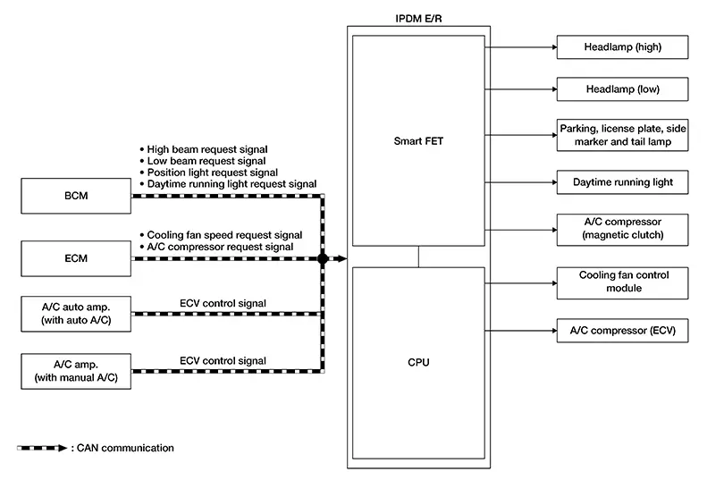
System Description
SYSTEM DIAGRAM
|
Component |
Function |
|---|---|
|
Smart FET |
Refer to Component Description. |
|
Headlamp (high) |
The IPDM E/R supplies power supply voltage to each lamp, and turns the each lamp ON. |
|
Headlamp (low) |
|
|
Parking, license plate, side marker and tail lamp |
|
|
Daytime running light |
|
|
A/C compressor (magnetic clutch) |
The IPDM E/R supplies power supply voltage to the A/C compressor (magnetic clutch), and turns the magnet clutch ON. |
|
Cooling fan control module |
The IPDM E/R controls each actuator. |
|
A/C compressor (ECV) |
INPUT SIGNAL AND OUTPUT SIGNAL
Major signal transmission between each unit via communication is shown in the following table:
|
Component parts |
Signal description |
|---|---|
|
BCM |
The BCM transmits the ON/OFF request signal for each lamp to IPDM E/R via CAN communication. |
|
ECM |
|
|
A/C auto amp.1 |
The A/C auto amp.1 or A/C amp.2 transmits the ECV control signal to the IPDM E/R via CAN communication. |
|
A/C amp.2 |
|
|
IPDM E/R |
|
1: Auto A/C
2: Manual A/C
Power Consumption Control System
System Description
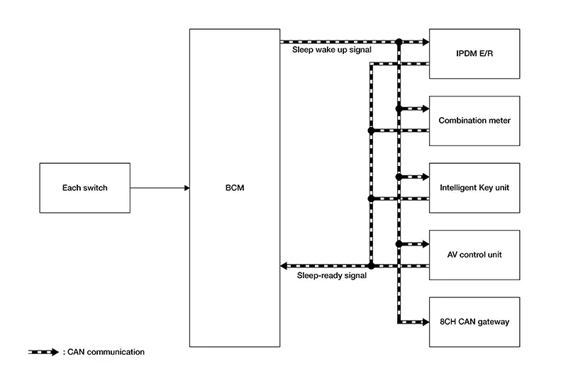
System Description
SYSTEM DIAGRAM
INPUT SIGNAL AND OUTPUT SIGNAL
Major signal transmission between each unit via communication is shown in the following table:
|
Component parts |
Signal description |
|---|---|
|
IPDM E/R |
|
|
Combination meter |
|
|
Intelligent Key unit |
|
|
AV control unit |
|
|
8CH CAN gateway |
|
|
BCM |
|
DESCRIPTION
Outline
-
The IPDM E/R incorporates a power consumption control function that reduces the power consumption according to the Nissan Sentra vehicle status.
-
The IPDM E/R changes its status (control mode) with the sleep wake up signal received from BCM via CAN communication.
Normal mode (wake-up)
-
CAN communication is normally performed with other control units.
-
Individual unit control by IPDM E/R is normally performed.
Low power consumption mode (sleep)
-
Low power consumption control is active.
-
CAN transmission is stopped.
-
Sleep Mode Activation
-
IPDM E/R judges that the sleep-ready conditions are fulfilled when the ignition switch is OFF and none of the conditions below are present. Then it transmits a sleep-ready signal (ready) to BCM via CAN communication.
-
Outputting signals to actuators
-
Switches or relays operating
-
Output requests are being received from control units via CAN communication.
-
-
IPDM E/R stops CAN communication and enters the low power consumption mode when it receives a sleep wake up signal (sleep) from BCM and the sleep-ready conditions are fulfilled.
Wake-up Operation
-
The IPDM E/R changes from the low power consumption mode to the normal mode when it receives a sleep wake-up signal (wake up) from the BCM or when any of the following conditions are fulfilled. In addition, it transmits a sleep-ready signal (not-ready) to the BCM via CAN communication to report the CAN communication start.
-
Ignition switch ON
-
An output request is received from a control unit via CAN communication.
-
Ignition Battery Saver Logic
If the ignition switch is ON for a period of time with the engine OFF, the IPDM E/R and BCM turn OFF to save the battery.
Signal Buffer System
System Description
System Description
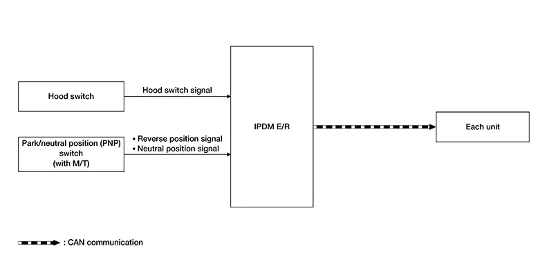
SYSTEM DIAGRAM
|
Component |
Function |
|---|---|
|
Park/neutral (PNP) switch * |
Transmits the neutral position signal to the IPDM E/R. |
|
Hood switch |
Detects the hood condition (open or close), and transmits the hood switch signal to the IPDM E/R. |
|
IPDM E/R |
The IPDM E/R has the signal transmission function that transmits each input signal to each unit. |
*: With M/T
Signal transmission function list
|
Signal name |
Input |
Output |
Description |
|---|---|---|---|
|
Reverse position signal |
Park/neutral (PNP) switch* |
Each unit (CAN) |
Inputs the reverse position signal and transmits it via CAN communication. |
|
Neutral position signal |
Park/neutral (PNP) switch* |
Each unit (CAN) |
Inputs the neutral position signal and transmits it via CAN communication. |
|
Hood switch signal |
Hood switch |
Each unit (CAN) |
Inputs the hood switch signal and transmits it via CAN communication. |
*: With M/T
Energy Managment System
System Description
System Description
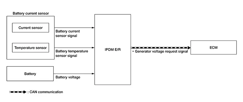
SYSTEM DIAGRAM
|
Component |
Function |
|
|---|---|---|
|
Battery current sensor |
Current sensor |
Detects the charging/discharging current of the battery. |
|
Temperature sensor |
Detects the temperature around the battery. |
|
|
Battery |
Battery supplies power supply voltage to each unit and parts. |
|
|
IPDM E/R |
The IPDM E/R transmits the generator voltage request signal to the ECM via CAN communication according to battery voltage and the battery temperature sensor signal. |
|
|
ECM |
The ECM controls power generation voltage to the generator according to the request from the IPDM E/R received via CAN communication. |
|
Signal transmission function list
|
Signal name |
Input |
Output |
Description |
|---|---|---|---|
|
Battery current sensor signal |
Battery current sensor |
IPDM E/R |
Transmits the battery current sensor signal to the IPDM E/R. |
|
Battery temperature sensor signal |
Battery current sensor |
IPDM E/R |
Transmits the battery temperature sensor signal to the IPDM E/R. |
|
Generator voltage request signal |
IPDM E/R |
ECM (CAN) |
Transmits the generator voltage request signal via CAN communication. |
SYSTEM DESCRIPTION
The IPDM E/R has an energy management system that recognizes the battery status from the battery current signal from the battery current sensor, the battery temperature sensor signal, and the battery voltage from the battery and maintains normal battery status. Refer to the following for details:
-
Charging system: Refer to System Description.
Other materials:
Parking Brake System. Foot Pedal
Precaution. Precautions
Precautions
Precaution for Supplemental Restraint System (srs) "air Bag" and "seat Belt Pre-Tensioner"
Precaution for Supplemental Restraint System (SRS) "AIR BAG" and "SEAT BELT PRE-TENSIONER"
The Supplemental Restraint System such as
“AIR BAG” and “SEAT BEL ...
Ecu Diagnosis Information. Bcm, Ipdm E/r, Intelligent Key Unit
Bcm, Ipdm E/r, Intelligent Key Unit
List of Ecu Reference
List of ECU
Reference
ECU
Reference
BCM
Values on the Diagnosis Too ...
Clutch. Removal and Installation
Clutch Pedal
Exploded View
Exploded View
1.
Clutch pedal
2.
Clutch master cylinder
...