Nissan Sentra B18 (2020-2025) Service Manual: System
Body Control System
System Description
System Description
OUTLINE
-
The BCM controls the various electrical components. It inputs the information required for control via CAN communication and the signal received from each switch and sensor.
-
The BCM has a combination switch reading function for reading the operation status of the combination switches (lighting, turn signal, wiper and washer) in addition to a function for controlling the operation of various electrical components. It also has the signal transmission function as the passed point of the signal and the a power saving control function that reduces the power consumption with the ignition switch OFF.
-
The BCM is equipped with the diagnosis function that performs diagnosis and various settings with CONSULT.
BCM CONTROL FUNCTION LIST
|
System |
Reference |
|
|---|---|---|
|
Combination switch reading system |
System Description |
|
|
Signal buffer system |
System Description |
|
|
Power consumption control system |
System Description |
|
|
Shipping mode control system |
System Description |
|
|
Auto light system |
System Description (Halogen headlamp) System Description (LED headlamp) |
|
|
Headlamp system |
System Description (Halogen headlamp) System Description (LED headlamp) |
|
|
HBA (high beam assist) system |
System Description (Halogen headlamp) System Description (LED headlamp) |
|
|
Daytime running light system |
System Description (Halogen headlamp) System Description (LED headlamp) |
|
|
Turn signal and hazard warning lamp system |
System Description (Halogen headlamp) System Description (LED headlamp) |
|
|
Parking, license plate, side marker and tail lamp system |
System Description (Halogen headlamp) System Description (LED headlamp) |
|
|
Stop lamp system |
System Description (Halogen headlamp) System Description (LED headlamp) |
|
|
Exterior lamp battery saver system |
System Description (Halogen headlamp) System Description (LED headlamp) |
|
|
Light reminder warning |
System Description (Halogen headlamp) System Description (LED headlamp) |
|
|
Headlamp warning |
System Description |
|
|
Illumination control system |
System Description |
|
|
Interior room lamp control system |
System Description |
|
|
Interior room lamp battery saver system |
System Description |
|
|
Front wiper and washer system |
System Description |
|
|
Rear window defogger system |
System Description |
|
|
Warning chime system |
System Description |
|
|
Power door lock system |
System Description |
|
|
Trunk lid opener system |
System Description |
|
|
Intelligent Key system/engine start function |
System Description |
|
|
Nissan anit-theft system (NATS) |
System Description |
|
|
Nissan Sentra Vehicle security system |
System Description |
|
|
Panic alarm |
||
|
Intelligent Key system |
Intelligent Key system |
System Description |
|
Remote engine start function |
System Description |
|
|
Remote keyless entry function |
System Description |
|
|
Door lock function |
System Description |
|
|
Warning function |
System Description |
|
|
Power window system |
System Description |
|
|
RAP (retained accessory power) system |
— |
|
|
TPMS (tire pressure monitoring system) |
System Description |
|
Combination Switch Reading System
System Description
System Description
SYSTEM DIAGRAM
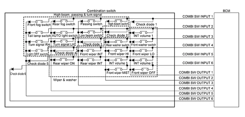
OUTLINE
-
The BCM reads the status of the combination switch and recognizes the status of each switch.
-
The BCM has a combination of 6 input terminals (INPUT 1 - 6) and 6 output terminals (OUTPUT 1 - 6) and reads a maximum of 22 switch states.
COMBINATION SWITCH MATRIX
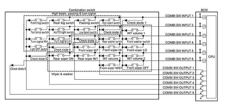
|
System |
INPUT 1 |
INPUT 2 |
INPUT 3 |
INPUT 4 |
INPUT 5 |
INPUT 6 |
|---|---|---|---|---|---|---|
|
OUTPUT 1 |
Check diode 1 |
INT volume 1 |
Front washer switch |
Front wiper LO |
INT volume 2 |
Front wiper OFF |
|
OUTPUT 2 |
High beam switch |
Check diode 2 |
Rear washer switch |
Front wiper HI |
INT volume 3 |
Front wiper MIST |
|
OUTPUT 3 |
Passing switch |
Low beam switch |
Check diode 3 |
Front wiper INT |
Rear wiper INT |
— |
|
OUTPUT 4 |
Rear fog switch |
AUTO light switch |
Turn signal LH |
Check diode 4 |
Rear wiper ON |
— |
|
OUTPUT 5 |
Front fog switch |
Tail lamp switch |
Turn signal RH |
Light OFF switch |
Check diode 5 |
— |
|
OUTPUT 6 |
— |
— |
— |
— |
— |
Check diode 6 |
COMBINATION SWITCH READING FUNCTION
Description
-
The BCM reads the status of the combination switch at 10 ms intervals normally.
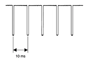
-
The BCM operates as follows and judges the status of the combination switch:
-
It operates the transistor on INPUT side in the following order: OUTPUT 6–> 5 –> 4 –> 3 –> 2 –> 1, and outputs voltage waveform.
-
The voltage waveform of OUTPUT corresponding to the formed circuit is input into the interface on the INPUT side if any (1 or more) switches are ON.
-
It reads this change of the voltage as the status signal of the combination switch.
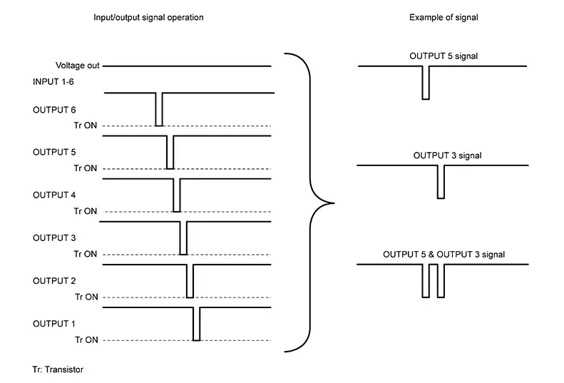
-
Operation Example
In the following operation example, the combination
of the status signals of the combination switch is replaced as follows:
INPUT 1 - 6 to “ -
-  � and OUTPUT 1
- 6 to “
� and OUTPUT 1
- 6 to “ -
-  �.
�.
Example 1: When a switch (turn signal RH) is turned ON
-
The circuit between INPUT 3 (
 ) and OUTPUT 5 (
 ) is formed when the turn signal RH is
turned ON.
) is formed when the turn signal RH is
turned ON.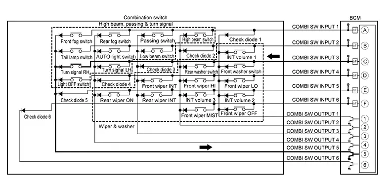
-
The BCM detects the combination switch status signal “
� when the signal of INPUT 3
is input
to OUTPUT 5. -
The BCM judges that the turn signal RH is ON when the signal “
� is detected.
Example 2: When multiple switches (front fog switch, turn signal RH) are turned ON
-
The circuits between INPUT 1 (
) and OUTPUT 5 () and between INPUT 3 () and
OUTPUT 5 () are formed when the front fog switch
and turn signal RH are turned ON.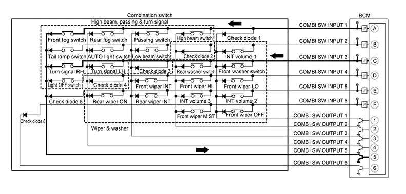
-
The BCM detects the combination switch status signal “
� when the signals of INPUT 1 and INPUT
3 are input to OUTPUT 5. -
The BCM judges that the front fog switch and turn signal RH are ON when the signal “
� is detected.
WIPER INTERMITTENT DIAL POSITION (WITH WIPER INTERMITTENT DIAL POSITION)
The BCM judges the wiper intermittent dial 1 - 5 by the status of INT volume 1, 2 and 3 switches.
|
Wiper intermittent dial position |
Switch status |
||
|---|---|---|---|
|
INT volume 1 |
INT volume 2 |
INT volume 3 |
|
|
1 |
ON |
ON |
OFF |
|
2 |
ON |
OFF |
OFF |
|
3 |
OFF |
OFF |
OFF |
|
4 |
OFF |
OFF |
ON |
|
5 |
OFF |
ON |
ON |

For details of wiper intermittent dial position, refer to System Description.
Signal Buffer System
System Description
System Description
SYSTEM DIAGRAM
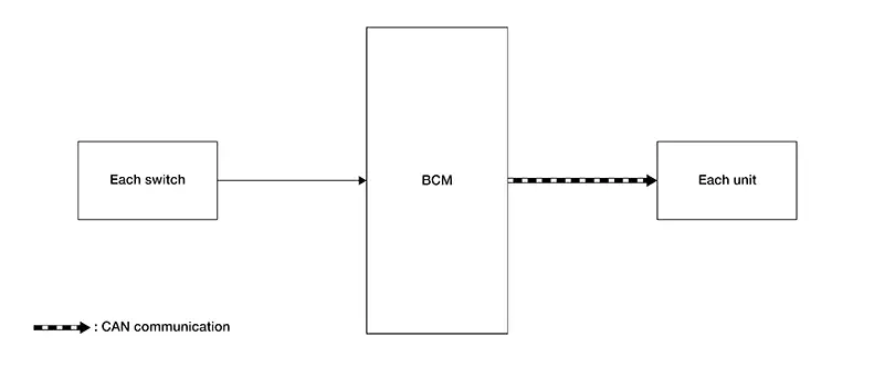
OUTLINE
The BCM has the signal transmission function that outputs/transmits each input/received signal to each unit.
Signal transmission function list
|
Signal name |
Input |
Output |
Description |
|---|---|---|---|
|
Stop lamp switch signal |
Stop lamp switch |
Each unit (CAN) |
Inputs the stop lamp switch signal and transmits it via CAN communication. |
|
Turn indicator signal |
Combination switch (lighting and turn signal switch) |
Each unit (CAN) |
Inputs the turn indicator signal and transmits it via CAN communication. |
Power Consumption Control System
System Description
System Description
SYSTEM DIAGRAM
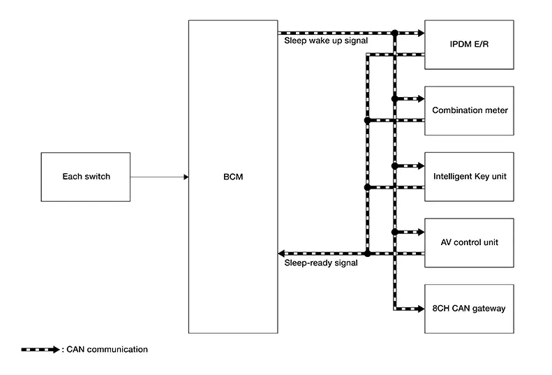
INPUT SIGNAL AND OUTPUT SIGNAL
Major signal transmission between each unit via communication is shown in the following table:
|
Component parts |
Signal description |
|---|---|
|
IPDM E/R |
|
|
Combination meter |
|
|
Intelligent Key unit |
|
|
AV control unit |
|
|
8CH CAN gateway |
|
|
BCM |
|
System Description
OUTLINE
-
The BCM incorporates a power saving control function that reduces power consumption according to the Nissan Sentra vehicle status.
-
The BCM switches the status (control mode) by itself with the power saving control function. It performs the sleep request to each unit (IPDM E/R and combination meter) that operates with the ignition switch OFF.
Normal mode (wake-up)
-
CAN communication is normally performed with other units
-
Each control with BCM is operating properly
CAN communication sleep mode (CAN sleep)
-
CAN transmission is stopped
-
Control with BCM only is operating
Low power consumption mode (BCM sleep)
-
Low power consumption control is active
-
CAN transmission is stopped
-
LOW POWER CONSUMPTION CONTROL WITH BCM
The BCM reduces power consumption with the following operation in low power consumption mode:
-
The reading interval of each switch changes from 10 ms interval to 60 ms interval.
Sleep mode activation
-
The BCM receives the sleep-ready signal (ready) from the IPDM E/R and combination meter via CAN communication.
-
The BCM transmits the sleep wake up signal (sleep) to each unit when all of the CAN sleep conditions are fulfilled.
-
Each unit stops the transmission of CAN communication with the sleep wakeup signal.
-
The BCM is in low power consumption mode and performs low power consumption control when all of the BCM sleep conditions are fulfilled with CAN sleep condition.
|
CAN sleep condition |
BCM sleep condition |
|---|---|
|
|
Wake-up operation
-
The BCM transmits the sleep wake up signal (wake up) to each unit when any of the CAN wake-up conditions are fulfilled. It changes from the low power consumption mode or the CAN communication sleep mode to the normal mode.
-
Each unit starts the transmission of CAN communication with the sleep wake up signal. In addition, the combination meter transmits the wake up signal to the BCM via CAN communication to report the CAN communication start.
|
BCM wake-up condition |
CAN wake-up condition |
|---|---|
|
|
Shipping Mode Control System
System Description
System Description
SYSTEM DIAGRAM
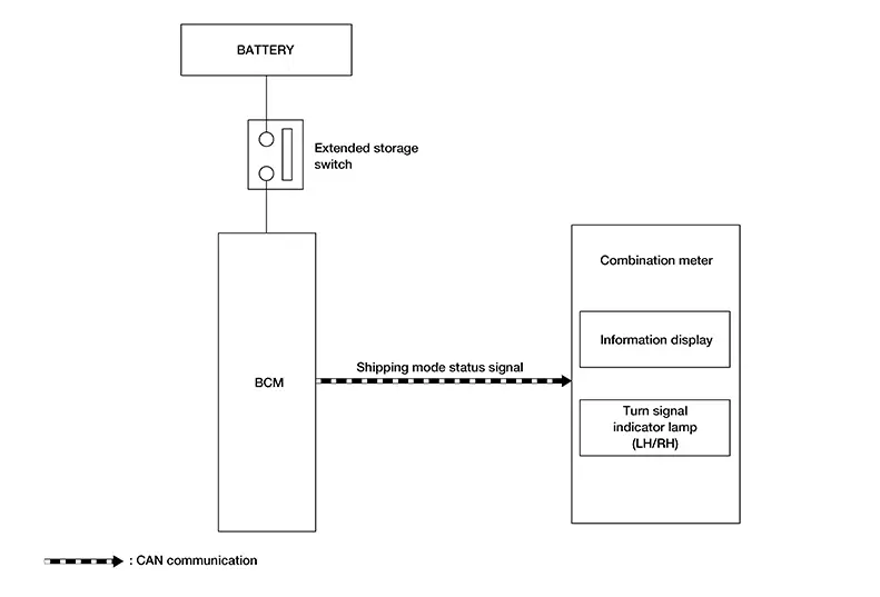
OUTLINE
The BCM has the shipping mode control system function that reduces the drain on the battery during extended storage.
Signal transmission function list
|
Signal name |
Input |
Output |
Description |
|---|---|---|---|
|
Shipping mode status signal |
BCM |
Combination meter (CAN) |
Transmits the shipping mode status signal via CAN communication. |
DESCRIPTION
-
The BCM switches the status (shipping mode or normal mode) by itself according to the extended storage switch condition, and transmits the shipping mode status signal to the combination meter and each unit via CAN communication.
-
When the shipping mode function is activated, the control units will not detect DTCs.
-
BCM control functions are limited in shipping mode. Refer to Description.
-
When the BCM is in shipping mode, a message may be shown in the combination meter or information display.
-
For shipping mode cancel operation, refer to Work Procedure.
Other materials:
Diagnosis System (intelligent Key Unit)
Consult Function (hands Free Module)
CONSULT Function
(HANDS FREE MODULE)
Intelligent Key unit
Refer to CONSULT Function
(HANDS FREE MODULE).
...
P1526 Vehicle Speed Sensor
Dtc Description
DTC Description
DTC DETECTION LOGIC
DTC
CONSULT screen terms
(Trouble diagnosis
content)
DTC detection
condition
...
C1f4f-82 Bcm Can Circuit 1
Dtc Description
DTC Description
DTC DETECTION LOGIC
DTC
CONSULT screen terms
(Trouble diagnosis
content)
DTC detection
conditi ...