Nissan Sentra B18 (2020-2025) Service Manual: Side Radar Lh
Values on the Diagnosis Tool
Values On The Diagnosis Tool
Note:
The following table includes information (items) inapplicable to this Nissan Sentra vehicle. For information (items) applicable to this vehicle, refer to CONSULT display items.
|
Monitor item |
Condition |
Value/Status |
|
|---|---|---|---|
|
Indicator |
Ignition switch ON |
When the warnings of the BSW system and RCTA system do not operate |
Off |
|
When the warning of the BSW system operates |
BSW |
||
|
When the warning of the RCTA system operates |
RCTA |
||
|
Side radar status |
Ignition switch ON |
When the side radar is normal |
Normal |
|
When the side radar is malfunction |
Malf |
||
|
Nissan Sentra Vehicle speed |
While drive |
Approximately equals the speedometer reading |
|
|
Turn signal |
Turn signal lamps OFF |
Off |
|
|
Turn signal lamp LH blinking |
LH |
||
|
Turn signal lamp RH blinking |
RH |
||
|
Shift position |
Engine running While driving |
P/R/N/D/M/L/No signal/Malf |
|
|
Transmission type |
Ignition switch ON |
When the transmission type is AT or CVT |
AT/CVT |
|
When the transmission type is MT |
MT |
||
|
When the transmission type is not select |
Unavailable |
||
|
Nissan Sentra Vehicle states |
Note:
The item is displayed, but it is not used |
- |
|
|
R range |
Ignition switch ON |
When the selector lever is in “R” position |
On |
|
When the selector lever is in any position other than “R” position |
Off |
||
|
When the selector lever is not select |
Unavailable |
||
|
Battery voltage |
Ignition switch ON |
V |
|
|
Yaw rate |
Nissan Sentra Vehicle stopped |
Approx. 0 deg/sec |
|
|
Turning right |
Negative value |
||
|
Turning left |
Positive value |
||
|
Warning status |
Ignition switch ON |
When the warnings of the BSW system and the RCTA system do not operate |
Off |
|
When the warning of the BSW system operates |
BSW |
||
|
When the warning of the RCTA system operates |
RCTA |
||
Physical Values
Physical Values
TERMINAL LAYOUT
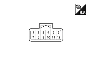
PHYSICAL VALUES
|
Terminal No. (Wire color) |
Description |
Condition |
Reference value |
||
|---|---|---|---|---|---|
|
+ |
– |
Signal name |
Input/Output |
||
|
1 (W) |
Ground |
BSW indicator signal |
Output |
Approx. 2 sec. after ignition switch OFF ⇒ ON (bulb check) |
Approx. 12 V |
|
5 (LG) |
— |
Chassis CAN communication2-L |
— |
— |
— |
|
6 (GR) |
— |
Chassis CAN communication2-H |
— |
— |
— |
|
7 (BR) |
Ground |
Ignition power supply |
Input |
Ignition switch ON |
Battery voltage |
|
8 (B) |
Switching signal |
— |
— |
0 V |
|
|
9 (B) |
Ground |
— |
— |
0 V |
|
Fail-Safe
Fail-safe
Refer to Fail-safe (Side Radar).
Dtc Inspection Priority Chart
DTC Inspection Priority Chart
If some DTCs are displayed at the same time, perform inspections one by one based on the following priority chart.
|
Priority |
Detected items (DTC) |
|---|---|
|
1 |
|
|
2 |
|
Dtc Index
DTC Index
Ă—: Applicable|
DTC |
Items (CONSULT screen terms) |
Fail-safe |
Reference page |
||
|---|---|---|---|---|---|
|
BSW |
RCTA |
||||
|
C1E00 |
44 |
Control unit |
Ă— |
Ă— |
DTC Description |
|
49 |
Control unit |
Ă— |
Ă— |
DTC Description |
|
|
C1E08 |
62 |
Control unit |
Ă— |
Ă— |
DTC Description |
|
C1E10 |
49 |
Side radar RH malfunction |
Ă— |
Ă— |
DTC Description |
|
C1E11 |
97 |
Side radar malfunction |
Ă— |
Ă— |
DTC Description |
|
C1E12 |
11 |
BSW/BSI IND SHORT CIR |
Ă— |
Ă— |
DTC Description |
|
15 |
BSW/BSI IND OPEN CIR |
Ă— |
Ă— |
DTC Description |
|
|
DTC |
Items (CONSULT screen terms) |
Fail-safe |
Reference page |
||
|---|---|---|---|---|---|
|
BSW |
RCTA |
||||
|
U007B |
00 |
Control module comm Bus I Off |
Ă— |
Ă— |
DTC Description |
|
U2141 |
87 |
CAN comm err (TCM) |
Ă— |
Ă— |
DTC Description |
|
U2148 |
87 |
CAN comm err (brake control unit) |
Ă— |
Ă— |
DTC Description |
|
U214E |
87 |
CAN comm err (combination meter) |
Ă— |
Ă— |
DTC Description |
|
U214F |
87 |
CAN comm err (BCM) |
Ă— |
Ă— |
DTC Description |
|
U2152 |
87 |
CAN comm err (ADAS control unit) |
Ă— |
Ă— |
DTC Description |
|
U215B |
87 |
CAN comm err (IPDM E/R) |
Ă— |
Ă— |
DTC Description |
|
U216E |
87 |
CAN comm err (side radar) |
Ă— |
Ă— |
DTC Description |
Other materials:
Warning/Indicator lights (other)
For additional details about warning and indicator functions in the Nissan Sentra,
refer to the sections titled "Vehicle information display 4.2 inch (11 cm) Type
A" or "Vehicle information display 7 inch (18 cm) Type B", depending on the equipment
installed in your vehicle ...
B24f4-12 Steering Heater Relay
Dtc Description
DTC Description
DTC DETECTION LOGIC
DTC No.
CONSULT screen terms (Trouble
diagnosis name)
DTC detection condition
...
U1040 Eng Comm Circuit
Dtc Description
DTC Description
DTC DETECTION LOGIC
DTC
CONSULT screen terms
(Trouble diagnosis
content)
DTC detection
condition
...