Nissan Sentra Service Manual: Removal and installation
BCM
Removal and installation
Note:
Before replacing BCM, perform “READ CONFIGURATION” to save or print current vehicle specification. Refer to BCS-61, "CONFIGURATION (BCM) : Description".
Removal
- Disconnect the negative battery terminal. Refer to pg-52, "removal and installation".
- Remove instrument lower panel LH and instrument side finisher LH. Refer to IP-21, "Removal and Installation".
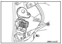
- Remove fuse block (j/b) screws (a) and position (bcm) aside.
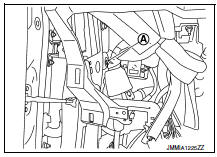
- Remove harness clip (a).
- Remove the screws (a) from the bcm (1).
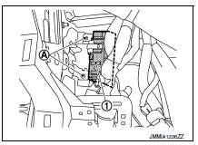
- Disconnect the harness connectors and remove the bcm.
Installation
Installation is in the reverse order of removal.
Caution:
- Perform “configuration (bcm)” when replacing bcm. Refer to bcs-61, "configuration (bcm) : description"
- Be sure to perform the system initialization (nats) when replacing bcm. Refer to bcs-60, "additional service when replacing control unit (bcm) : work procedure".
- When replacing bcm, if new bcm does not come with keyfobs attached, all existing keyfobs must be re-registered. Refer to the consult immobilizer mode and follow the on-screen instructions.
Combination switch
Exploded view
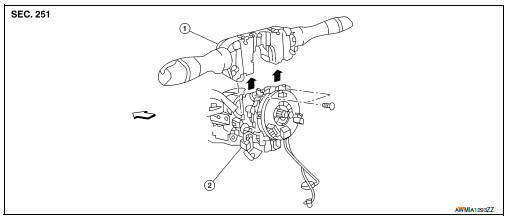
- Combination switch
- Combination switch harness connector
 Front
Front
Note:
Shown with the steering wheel removed for clarity only.
Removal and installation
Removal
Caution:
- Before servicing, turn the ignition switch off, disconnect both battery terminals and wait at least three minutes.
- Do not use air or electric tools when removing or installing the combination switch.
- Disconnect both the negative and positive battery terminals, then wait at least three minutes. Refer to pg- 50, "removal and installation (battery)".
- Remove the steering column covers. Refer to ip-16, "removal and installation".
- Rotate steering wheel clockwise to access first combination switch bolt and remove.
- Rotate steering wheel counter-clockwise to access second combination switch bolt and remove.
- Disconnect the harness connector from the combination switch and remove.
Installation
Installation is in the reverse order of removal.
Caution:
- After the work is completed, make sure no system malfunction is detected by air bag warning lamp.
- In case a malfunction is detected by the air bag warning lamp, reset with the self-diagnosis function and delete the memory with consult.
- If a malfunction is still detected after the above operation,
perform self-diagnosis to repair malfunctions.
Refer to src-41, "additional service when replacing control unit : special repair requirement".
 Symptom diagnosis
Combination switch system symptoms
Symptom Table
Perform the data monitor of consult to check for any malfunctioning
item.
Check the malfunction combinations.
Identify the malfunct ...

Other materials:
Washer tank
Exploded view
Washer tank inlet
Washer tank
Washer level switch
Washer tank seal
Washer pump
Removal and installation
REMOVAL
Drain the washer fluid.
Remove the front under cover. Refer to ext-30, "front under cover :
removal and installation".
Remove the fe ...
Moonroof unit assembly
Inspection
WIND DEFLECTOR
Open glass lid fully
Visually check for proper installation, damaged/deteriorated components,
or foreign objects within mechanism.
Correct as required for smooth operation.
Check for grease at the wind deflector arm (1) and pivot areas. If
necessary, apply ...
Precaution for Supplemental Restraint System (SRS) "AIR BAG"
and "SEAT BELT PRE-TENSIONER"
The Supplemental Restraint System such as “AIR BAG” and “SEAT
BELT PRE-TENSIONER”, used along
with a front seat belt, helps to reduce the risk or severity of injury to the
driver and front passenger for certain
types of collision. Information necessary to service the system ...
