Nissan Sentra B18 (2020-2025) Service Manual: Rear View Camera Image Signal Circuit
Diagnosis Procedure
-
CHECK CAMERA POWER SUPPLY CIRCUIT CONTINUITY
-
-
Ignition switch OFF.
-
Disconnect AV control unit connector and rear view camera connector.
-
Check continuity between AV control unit connector and rear view camera connector.
AV control unit
Rear view camera
Continuity
Connector
Terminal
Connector
Terminal
M104
33
B30
1
Yes
-
Check continuity between AV control unit connector and ground.
AV control unit
ŌĆö
Continuity
Connector
Terminal
M104
33
Ground
No
-
Is inspection result normal?
YES >>GO TO 2.
NO >>Repair or replace harness or connectors.
-
-
CHECK CAMERA POWER SUPPLY VOLTAGE
-
-
Connect AV control unit connector and rear view camera connector.
-
Ignition switch ON.
-
Shift the selector lever to R (reverse).
-
Check voltage between AV control unit connector and ground.
AV control unit
(ŌłÆ)
Condition
Voltage
(Approx.)
(+)
Connector
Terminal
M104
33
Ground
Selector lever is in ŌĆ£RŌĆØ.
6.0 V
-
Is inspection result normal?
YES >>GO TO 3.
NO >>Replace AV control unit. Refer to Removal and Installation.
-
-
CHECK CAMERA IMAGE SIGNAL CIRCUIT CONTINUITY
-
-
Ignition switch OFF.
-
Disconnect AV control unit connector and rear view camera connector.
-
Check continuity between AV control unit connector and rear view camera connector.
AV control unit
Rear view camera
Continuity
Connector
Terminal
Connector
Terminal
M104
52
B30
3
Yes
-
Check continuity between AV control unit connector and ground.
AV control unit
ŌĆö
Continuity
Connector
Terminal
M104
52
Ground
No
-
Is inspection result normal?
YES >>GO TO 4.
NO >>Repair or replace harness or connectors.
-
-
CHECK CAMERA GROUND CIRCUIT CONTINUITY
-
Check continuity between AV control unit connector and rear view camera connector.
AV control unit
Rear view camera
Continuity
Connector
Terminal
Connector
Terminal
M104
32
B30
2
Yes
Is inspection result normal?
YES >>GO TO 5.
NO >>Repair or replace harness or connectors.
-
-
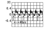
CHECK CAMERA IMAGE SIGNAL
-
-
Connect AV control unit connector and rear view camera connector.
-
Ignition switch ON.
-
Shift the selector lever to R (reverse).
-
Check signal between AV control unit connector and ground.
AV control unit
(ŌłÆ)
Condition
Reference value
(+)
Connector
Terminal
M104
52
Ground
Camera image displayed.
-
Is inspection result normal?
YES >>Replace AV control unit. Refer to Removal and Installation.
NO >>Replace rear view camera. Refer to Removal and Installation.
-
 Power Supply and Ground Circuit
Av Control Unit
Diagnosis Procedure
Diagnosis Procedure
CHECK FUSE
Check that the following fuse is not blown:
...

Other materials:
Hazard Switch
Component Inspection
Component Inspection
CHECK HAZARD SWITCH
Ignition switch OFF.
Disconnect hazard switch connector.
Check continuity between hazar ...
Anti-lock Braking System (ABS)
WARNING
The Anti-lock Braking System (ABS) is a
sophisticated device, but it cannot prevent
accidents resulting from careless
or dangerous driving techniques. It can
help maintain vehicle control during
braking on slippery surfaces. Remember
that stopping distances ...
B2231-16 Battery Voltage
Dtc Description
DTC Description
DTC DETECTION LOGIC
DTC No.
CONSULT screen terms
(Trouble diagnosis
content)
DTC detected condition
...
