Nissan Sentra B18 (2020-2025) Service Manual: Rear Seat
Exploded View
Exploded View
60:40 SPLIT SEATBACK
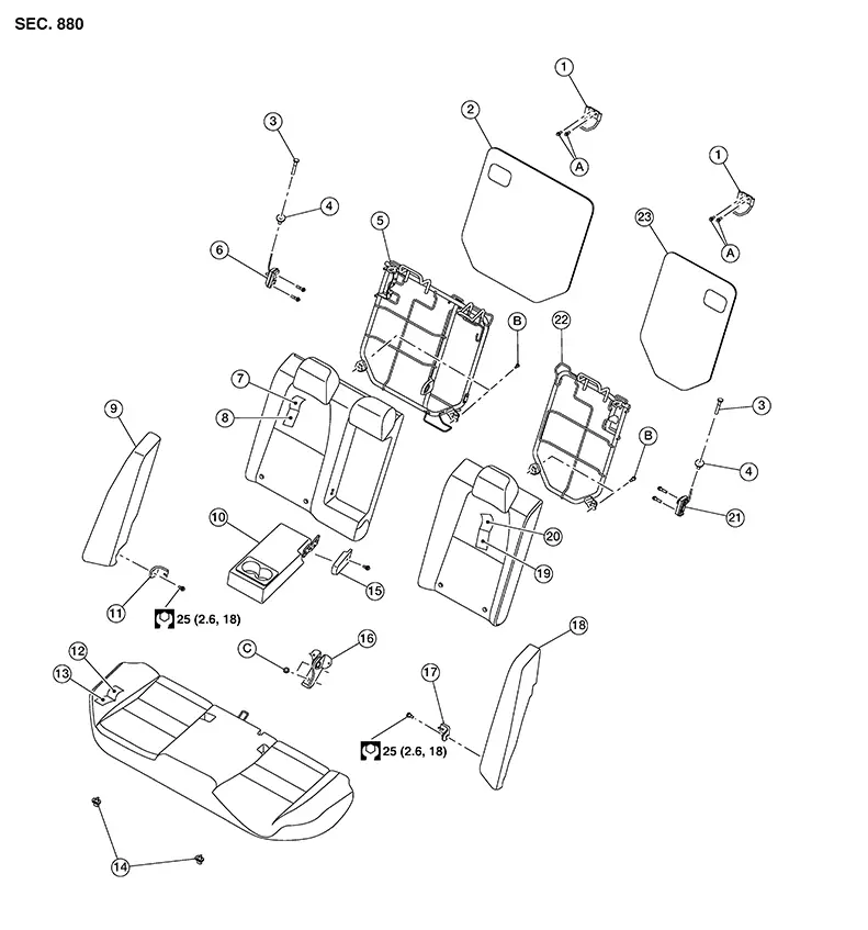
|
1. |
Seatback striker |
2. |
Rear seatback insulator (RH) |
3. |
Seatback latch release knob |
|
4. |
Seatback latch release knob finisher |
5. |
Rear seatback frame (RH) |
6. |
Seatback latch assembly (RH) |
|
7. |
Seatback trim (RH) |
8. |
Seatback pad (RH) |
9. |
Rear seat bolster (RH) |
|
10. |
Armrest assembly (if equipped) |
11. |
Seatback hinge bracket (RH) |
12. |
Seat cushion trim |
|
13. |
Seat cushion pad |
14. |
Seat cushion hook |
15. |
Armrest hinge finisher (if equipped) |
|
16. |
Seatback hinge bracket (center) |
17. |
Seatback hinge bracket (LH) |
18. |
Seatback bolster (LH) |
|
19. |
Seatback pad (LH) |
20. |
Seatback trim (LH) |
21. |
Seatback latch assembly (LH) |
|
22. |
Rear seatback frame (LH) |
23. |
Rear seatback insulator (LH) |
A. |
Refer to Removal and Installation |
|
B. |
Refer to Removal and Installation |
C. |
Refer to Removal and Installation |
Removal and Installation - Seat Cushion Assembly
Removal and Installation - Seat Cushion Assembly
REMOVAL
Lift up the seat cushion assembly close to the front edge (B) to release it from the seat cushion hooks (A) (one for each side).
Remove the rear seatback assembly. Refer to Removal and Installation - 60:40 Split Seatback.
Remove the
seat cushion assembly. 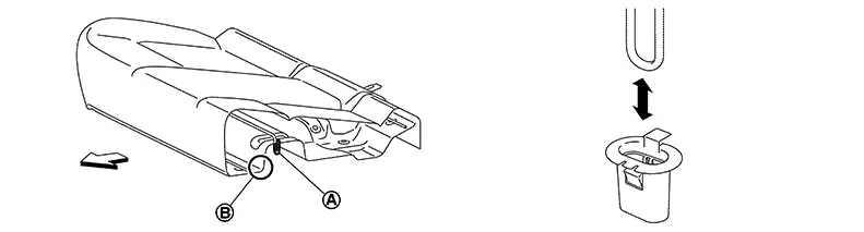
INSTALLATION
Installation is in the reverse order of removal.
Removal and Installation - 60:40 Split Seatback
Removal and Installation - 60:40 Split Seatback
REMOVAL
Place the rear seatback assembly in the folded down position.
Release the
hook fasteners (A) in the lower corners of the rear seatback
assembly. 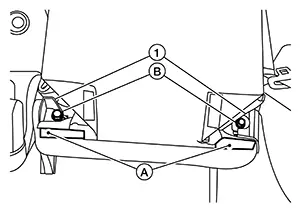
Remove the rear seatback assembly bolts (B) from the seatback hinge brackets (1), then remove the rear seatback assembly.
INSTALLATION
Installation is in the reverse order of removal.
Note:
-
When installing the rear seatback assembly, tighten bolts to specification in the order shown.
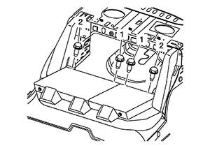
Rear seatback assembly bolt torque
: 21.1 N·m (2.2 kg-m, 16 lb-ft)
Removal and Installation - Armrest Assembly
Removal and Installation - Armrest Assembly
REMOVAL
Note:
RH shown, LH similar.
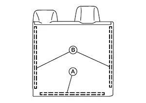
Place the rear seatback assembly (RH) in the folded down position.
Release the
J-hook retainer (A) and unzip the seatback trim zippers (B).
Remove rear seatback insulator (RH).
Using a suitable tool remove clip then armrest hinge finisher. Refer to Exploded View.
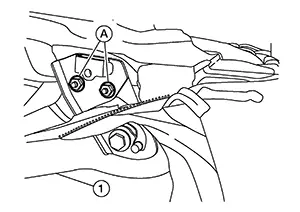
Remove nuts
(A) then the armrest assembly (1).
INSTALLATION
Installation is in the reverse order of removal.
Removal and Installation - Rear Seat Bolster
Removal and Installation - Rear Seat Bolster
REMOVAL
Warning:
Do not leave any objects (screwdrivers, tools, etc.) on the rear seat bolster during seat repair. It can lead to personal injury if the side air bag module should accidentally deploy.
CAUTION:
-
When removing or installing the rear seat bolster, handle it carefully to keep dirt out and to avoid damage.
-
Do not drop, tilt, or bump the side air bag module while installing the rear seat bolster. Always handle it with care.
-
After rear side air bag module inflates, the rear seat bolster must be replaced.
-
When removing and installing the rear seat bolster, use shop cloths to protect components from damage.
-
Before removing the rear seat bolster, turn the ignition switch OFF, disconnect both battery cables and wait at least three minutes.
Remove the seat cushion assembly. Removal and Installation.
Remove the bolt at bottom of rear seat bolster.
Disconnect the battery or batteries and wait at least three minutes. Refer to Battery Disconnect.
Disconnect
harness connector from the rear side air bag module. Note:
Take note of harness routing and attachment locations for correct installation.
Remove the rear seat bolster.
INSTALLATION
Installation is in the reverse order of removal.
CAUTION:
Make sure that the seat harness is not damaged during installation.
-
Tighten the pivot bolt to specification.
Exploded View.
Removal and Installation - Seat Cushion Hook
Removal and Installation - Seat Cushion Hook
REMOVAL
Remove the seat cushion assembly. Refer to Removal and Installation - Seat Cushion Assembly.
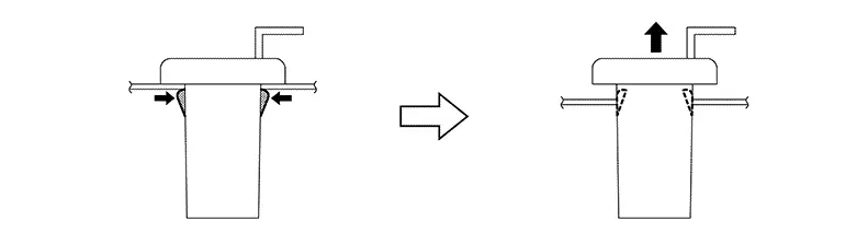
Using a suitable tool, release the seat cushion hook pawls as shown and remove.
CAUTION:
Before removing/installing the seat cushion hook, check its orientation (front/rear).
INSTALLATION
Installation is in the reverse order of removal.
Removal and Installation - Seatback Striker
Removal and Installation - Seatback Striker
REMOVAL
Remove rear seat bolster (LH/RH). Refer to Removal and Installation.
Using a suitable tool, remove clips then rear seat back finisher. Refer to Exploded View.
Remove the seatback striker bolts then seatback strikers. Refer to Exploded View.
INSTALLATION
Installation is in the reverse order of removal.
Note:
-
When installing the seat back striker, tighten bolts to specification in the order shown.
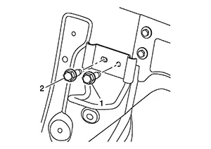
Seat back striker bolt torque
: 50 N·m (5.1 kg-m, 37 ft-lb)
Removal and Installation - Seatback Hinge Bracket
Removal and Installation - Seatback Hinge Bracket
REMOVAL
Remove the rear seatback assemblies (LH/RH). Refer to Removal and Installation - 60:40 Split Seatback.
Remove the seat cushion assembly. Refer to Removal and Installation - Seat Cushion Assembly.
Remove rear
seatback hinge bracket bolts (A) and remove.
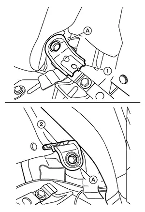
(1): Seatback hinge bracket (RH)
(2): Seatback hinge bracket (LH)
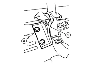
Remove rear
bolts (A) and seatback hinge bracket [center (1)].
INSTALLATION
Installation is in the reverse order of removal.
Note:
-
When installing the seat back bracket (center), tighten bolts to specification in the order shown.
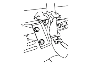
Seat back hinge (center) bolt torque
: 50N·m (5.1 kg-m, 37 lb-ft)
Other materials:
Precaution. Precautions
Precautions
Precaution for Supplemental Restraint System (srs) "air Bag" and "seat Belt Pre-Tensioner"
Precaution for Supplemental Restraint System (SRS) "AIR BAG" and "SEAT BELT PRE-TENSIONER"
The Supplemental Restraint System such as
“AIR BAG� and “SEAT BELT PRE-TENSIONER�,
u ...
Types of tires
WARNING
When changing or replacing tires on your Nissan Sentra, always ensure
that all four tires are of the same type (Summer, All Season, or Snow) and the
same construction. A NISSAN dealer can assist you in selecting the correct tire
type, size, speed rating, and availability suitabl ...
Diagnosis System (intelligent Key Unit)
Consult Function (hands Free Module)
CONSULT Function
(HANDS FREE MODULE)
Intelligent Key unit
Refer to CONSULT Function
(HANDS FREE MODULE).
...