Nissan Sentra B18 (2020-2025) Service Manual: Power Supply, Ground & Circuit Elements :: System Description
Component Parts. Electrical Units Location. Electrical Units Location
Component Parts Location
Component Parts Location
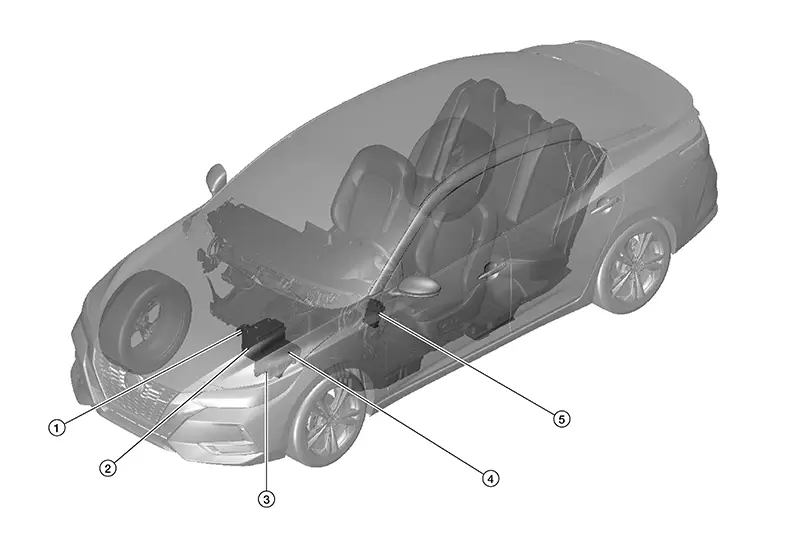
|
No. |
Component |
|---|---|
|
1. |
Fusible Link Box (Battery) |
|
2. |
Battery |
|
3. |
Fuse, Fusible Link and Relay Box |
|
4. |
IPDM E/R (Intelligent Power Distribution Module Engine Room) |
|
5. |
Fuse Block Junction Box (J/B) |
System. Power Supply, Ground & Circuit Elements. Power Supply, Ground & Circuit Elements
Harness Connector
Harness Connector
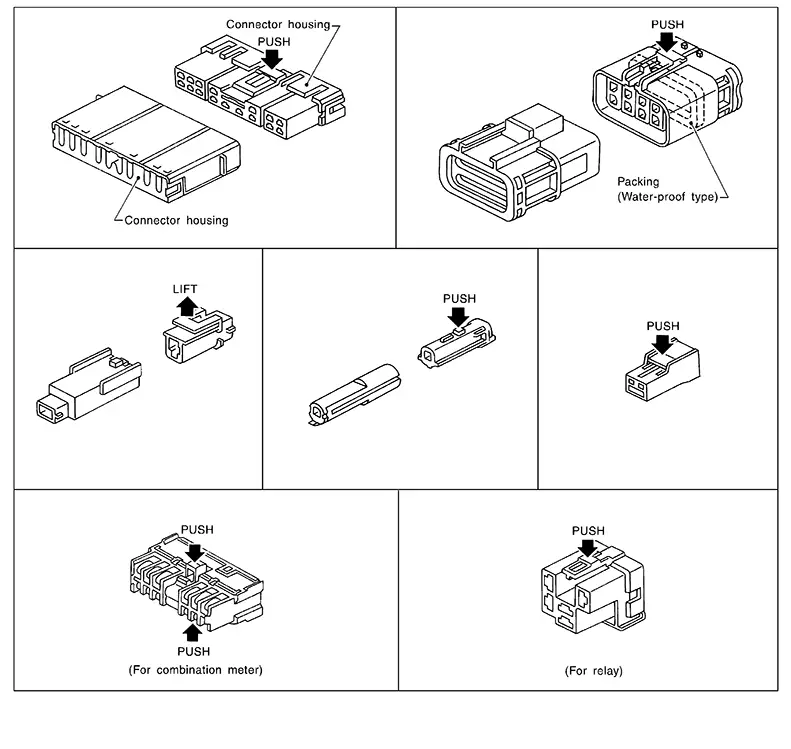
HARNESS CONNECTOR (TAB-LOCKING TYPE)
-
The tab-locking type connectors help prevent accidental looseness or disconnection.
-
The tab-locking type connectors are disconnected by pushing or lifting the locking tab(s). Refer to the figure below.
Refer to the next page for description of the slide-locking type connector.
CAUTION:
Do not pull the harness or wires when disconnecting the connector.
[Example]
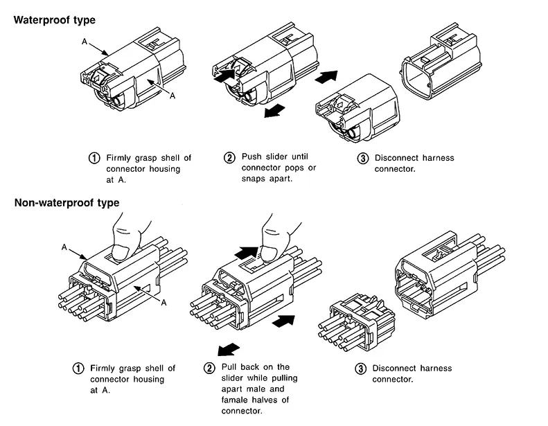
HARNESS CONNECTOR (SLIDE-LOCKING TYPE)
-
A new style slide-locking type connector is used on certain systems and components, especially those related to OBD.
-
The slide-locking type connectors help prevent incomplete locking and accidental looseness or disconnection.
-
The slide-locking type connectors are disconnected by pushing or pulling the slider. Refer to the figure below.
CAUTION:
-
Do not pull the harness or wires when disconnecting the connector.
-
Be careful not to damage the connector support bracket when disconnecting the connector.
[Example]
HARNESS CONNECTOR (LEVER LOCKING TYPE)
-
Lever locking type harness connectors are used on certain control units and control modules such as ECM, ABS actuator and electric unit (control unit), etc.
-
Lever locking type harness connectors are also used on super multiple junction (SMJ) connectors.
-
Always confirm the lever is fully locked in place by moving the lever as far as it will go to ensure full connection.
CAUTION:
-
Always confirm the lever is fully released (loosened) before attempting to disconnect or connect these connectors to avoid damage to the connector housing or terminals.
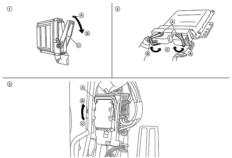
|
1. |
Control unit with single lever |
2. |
Control unit with dual lever |
3. |
SMJ connector |
|
A. Fasten |
A. Lever |
A. Lever |
|||
|
B. Loosen |
B. Fasten |
B. Fasten |
|||
|
C. Lever |
C. Loosen |
C. Loosen |
Standardized Relay
Standardized Relay
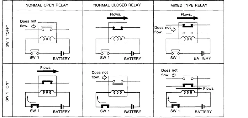
NORMAL OPEN, NORMAL CLOSED AND MIXED TYPE RELAYS
Relays can mainly be divided into three types: normal open, normal closed and mixed type relays.
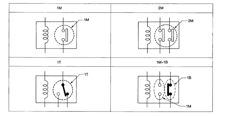
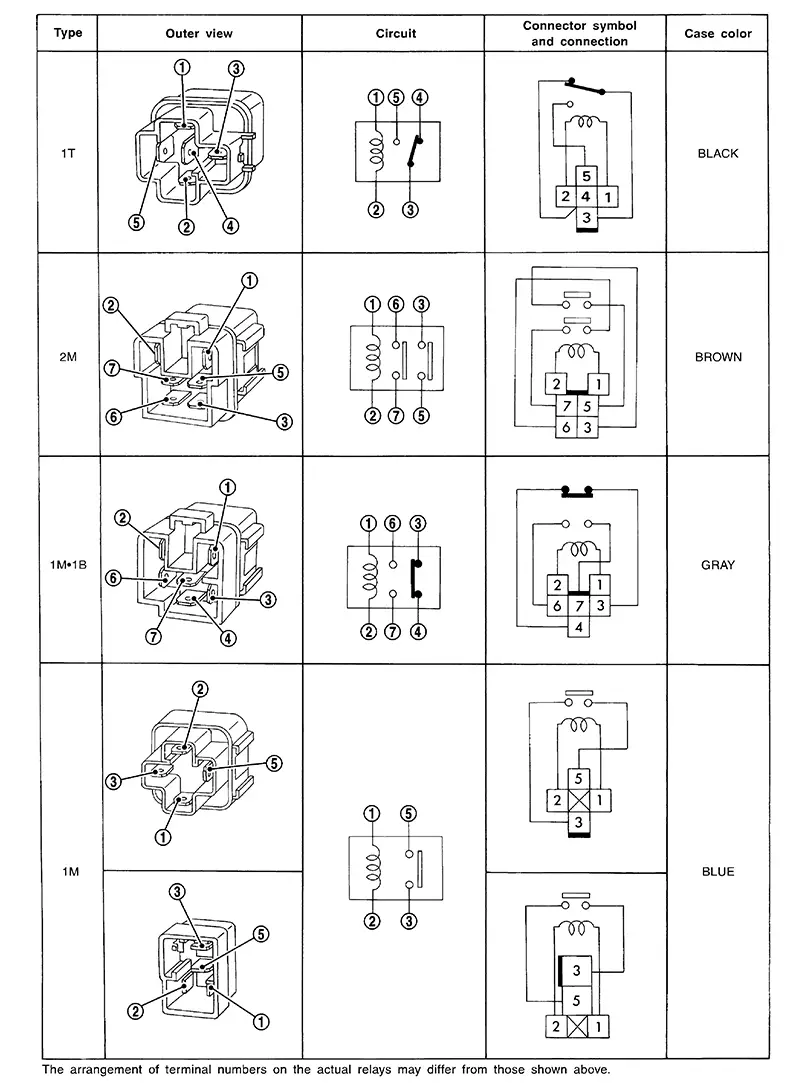
TYPE OF STANDARDIZED RELAYS
|
1M ···················· 1 Make |
2M ···················· 2 Make |
|
1T ···················· 1 Transfer |
1M·1B ···················· 1 Make 1 Break |
Other materials:
Fuel Pump
Component Inspection
Component Inspection
CHECK FUEL PUMP
Turn ignition switch OFF.
Disconnect “fuel level sensor
unit and fuel pump” harness connector.
Check the resistance between
...
Fuel Level Sensor Signal Circuit
Component Function Check
Component Function
Check
COMBINATION METER INPUT SIGNAL
CONSULT
Select “FUEL METER” in “Data Monitor” mode of “METER/M&A”.
Compare the ...
P0078 Evt Control Solenoid Valve
Dtc Description
DTC Description
DTC DETECTION LOGIC
DTC
CONSULT screen terms
(Trouble diagnosis
content)
DTC detection
condition
...