Nissan Sentra Service Manual: Power supply and ground circuit
Combination meter
Combination meter : diagnosis procedure
Regarding Wiring Diagram information, refer to MWI-28, "Wiring Diagram".
1.Check fuses
Check that the following fuses are not blown.
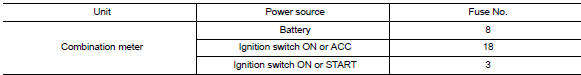
Is the fuse blown? YES >> Replace the blown fuse after repairing the affected circuit.
NO >> GO TO 2.
2.Power supply circuit check
Check voltage between combination meter harness connector M24 terminals 15, 27, 28 and ground.
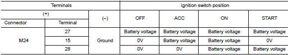
Is the inspection result normal? YES >> GO TO 3.
NO >> Repair or replace harness or connector.
3.Check ground circuit
Check continuity between combination meter harness connector m24 terminals 21, 22, 23 and ground.
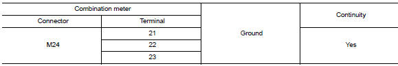
Is the inspection result normal? Yes >> inspection end.
No >> repair or replace harness or connector.
Bcm (body control system) (with intelligent key system)
Bcm (body control system) (with intelligent key system) : diagnosis procedure
Regarding wiring diagram information, refer to bcs-51, "wiring diagram".
1.Check fuses and fusible link
Check that the following fuses and fusible link are not blown.
Is the fuse blown? Yes >> replace the blown fuse or fusible link after repairing the affected circuit.
No >> go to 2.
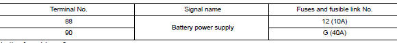
2.Check power supply circuit
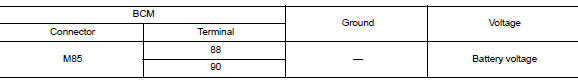
- Disconnect bcm connector m85.
- Check voltage between bcm connector m85 and ground.
Is the inspection result normal? Yes >> go to 3.
No >> repair harness or connector.
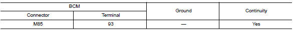
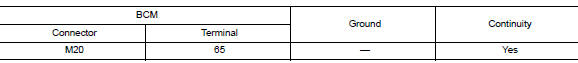
3.Check ground circuit
Check continuity between bcm connector m85 and ground.
Is the inspection result normal? Yes >> inspection end.
No >> repair harness or connector.
Bcm (body control system) (without intelligent key system)
Bcm (body control system) (without intelligent key system) : diagnosis procedure
Regarding wiring diagram information, refer to bcs-111, "wiring diagram".
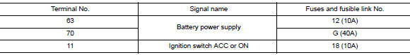
1.Check fuses and fusible link
Check that the following fuses and fusible link are not blown.
Is the fuse blown?
Yes >> replace the blown fuse or fusible link after repairing the affected circuit.
No >> go to 2.
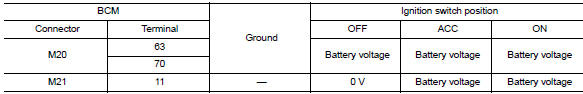
2.Check power supply circuit
- Turn ignition switch off.
- Disconnect bcm connectors.
- Check voltage between bcm connector and ground.
Is the inspection result normal? YES >> GO TO 3.
NO >> Repair harness or connector.
3.Check ground circuit
Check continuity between bcm connector and ground.
Is the inspection result normal? Yes >> inspection end.
No >> repair harness or connector.

 Meter buzzer circuit
Description
The buzzer for warning chime system is installed in the combination
meter.
The combination meter sounds the alarm buzzer based on the signals
transmitted from various units.
...
Other materials:
P0128 Thermostat function
DTC Logic
DTC DETECTION LOGIC
NOTE:
If DTC P0128 is displayed with DTC P0300, P0301, P0302, P0303 or P0304,
first perform the trouble
diagnosis for P0300, P0301, P0302, P0303 or P0304. Refer to EC-269, "DTC Logic".
Engine coolant temperature has not risen enough to open the thermost ...
Unit disassembly and assembly
Front coil spring and strut
Exploded View
Piston rod lock nut
Strut mount insulator
Strut mount bearing
Bound bumper
Coil spring
Lower rubber seat
Strut
Steering knuckle
Front
Disassembly and Assembly
DISASSEMBLY
CAUTION:
Do not damage the piston rod when removing comp ...
Ecu diagnosis information
ECM
Reference Value
VALUES ON THE DIAGNOSIS TOOL
NOTE:
The following table includes information (items) inapplicable to this
vehicle. For information (items) applicable
to this vehicle, refer to CONSULT display items.
Numerical values in the following table are reference values.
Thes ...
