Nissan Sentra B18 (2020-2025) Service Manual: Parking Brake System :: Hand Lever
Precaution. Precautions. Precautions
Precaution for Supplemental Restraint System (srs) "air Bag" and "seat Belt Pre-Tensioner"
Precaution for Supplemental Restraint System (SRS) "AIR BAG" and "SEAT BELT PRE-TENSIONER"
The Supplemental Restraint System such as “AIR BAG� and “SEAT BELT PRE-TENSIONER�, used along with a front seat belt, helps to reduce the risk or severity of injury to the driver and front passenger for certain types of collisions.
Information necessary to service the system safely is included in the “SRS AIR BAG� and “SEAT BELT� sections of this Service Manual.
Warning:
Always observe the following items for preventing accidental activation:
-
To avoid rendering the SRS inoperative, which could increase the risk of personal injury or death in the event of a collision that would result in air bag inflation, it is recommended that all maintenance and repair be performed by an authorized NISSAN/INFINITI dealer.
-
Improper repair, including incorrect removal and installation of the SRS, can lead to personal injury caused by unintentional activation of the system. For removal of Spiral Cable and Air Bag Module, see “SRS AIR BAG�.
-
Never use electrical test equipment on any circuit related to the SRS unless instructed to in this Service Manual. SRS wiring harnesses can be identified by yellow and/or orange harnesses or harness connectors.
PRECAUTIONS WHEN USING POWER TOOLS (AIR OR ELECTRIC) AND HAMMERS
Warning:
Always observe the following items for preventing accidental activation:
-
When working near the Air Bag Diagnosis Sensor Unit or other Air Bag System sensors with the ignition/power switch ON or engine running, never use air or electric power tools or strike near the sensor(s) with a hammer. Heavy vibration could activate the sensor(s) and deploy the air bag(s), possibly causing serious injury.
-
When using air or electric power tools or hammers, always switch the ignition/power switch OFF, disconnect the 12V battery or batteries, and wait at least 3 minutes before performing any service.
Preparation. Preparation. Preparation
Commercial Service Tool
Commercial Service Tool
|
Tool name |
Description |
|
|---|---|---|
|
Power tool |
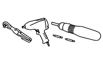 |
Loosening nuts, screws and bolts |
Periodic Maintenance. Parking Brake System. Parking Brake System
Inspection
Inspection
INSPECTION
Lever Stroke
Operate the parking brake lever with a force of 196 N (20.0 kg-f, 44.1 lb-f). Check that the lever stroke is within the specified number of notches. (Check it by listening to the clicks of the ratchet.)
|
Number of notches |
: Refer to Parking Brake Control. |
When brake warning lamp turns ON, check that the lever stroke is within the specified number of notches. (Check it by listening to the clicks of the ratchet.)
|
Number of notches |
: Refer to Parking Brake Control. |
Inspect Components
-
Make sure that the attachment conditions (looseness, backlash, etc.) of each component are normal.
-
Check the following:
-
Device assembly for bends, damage and cracks. Replace if any damage is noted.
-
Cables and equalizer for wear and damage. Replace if any damage is noted.
-
Parking brake switch. Replace if it does not work correctly.
-
Adjustment
Adjustment
ADJUSTMENT
Remove the cup holder finisher. Refer to Exploded View.
Pull the parking brake lever.
Insert a
suitable tool onto the adjusting nut (A) and rotate the adjusting
nut to fully loosen the cable, then release the parking brake
lever. 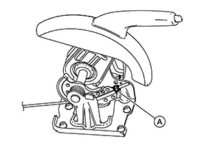
CAUTION:
Do not reuse the adjusting nut if the nut is removed.
Note:
It is not necessary to remove the adjusting nut.
Depress the brake pedal with a force of 196 N (20.0 kg-f, 44.1 lb-f) about 10 times with the engine on.
CAUTION:
Make sure to securely operate the brake pedal.
Check that there is no drag on the rear disc brake rotor when the brake pedal is released. If any rear disc brake rotor drag is found, perform the following procedure: Remove the brake pads. Refer to Removal and Installation. Using a suitable tool, turn the piston into the brake caliper body.
CAUTION:
Do not damage the piston boot.
Install the brake pads. Depress the brake pedal several times. Check the drag of the rear disc brake again. If any drag is found, disassemble the brake caliper body. Refer to Disassembly and Assembly.Adjust the cable with the following procedure: Adjust the parking brake lever stroke by turning the adjusting nut using a suitable tool.
CAUTION:
-
Do not reuse the adjusting nut if the nut is removed.
-
To prevent damage, do not bend parking brake cables.
|
Number of notches |
: Refer to Parking Brake Control. |
CAUTION:
If any drag is found, verify the parking brake components are installed and adjusted correctly.
Install the cup holder finisher. Refer to Exploded View.
Removal and Installation. Parking Brake Control
Exploded View
Exploded View
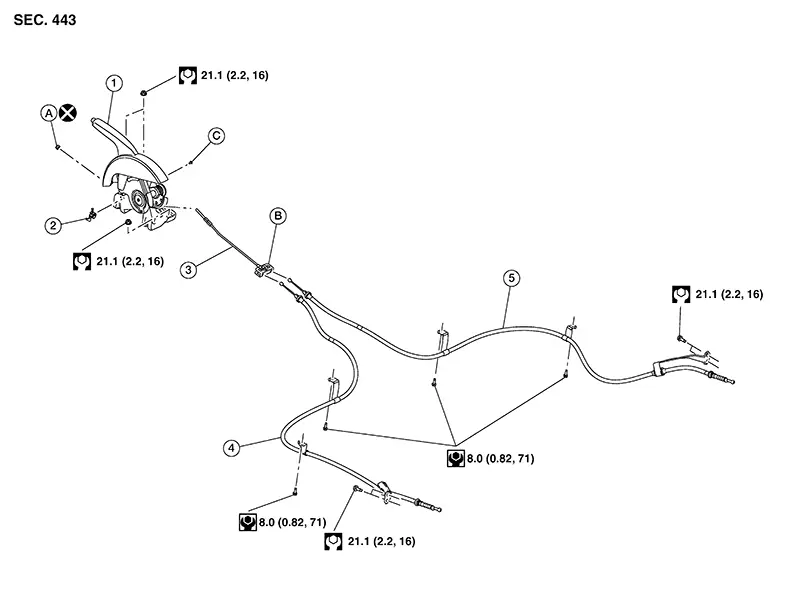
|
1. |
Parking brake lever assembly |
2. |
Parking brake switch |
3. |
Front parking brake cable |
|
4. |
Rear parking brake cable (LH) |
5. |
Rear parking brake cable (RH) |
A. |
Adjusting nut |
|
B. |
Equalizer |
C. |
Screw |
Removal and Installation
Removal and Installation
REMOVAL
Remove the cup holder finisher. Refer to Exploded View.
Loosen the
adjusting nut (A).
CAUTION:
Do not reuse the adjusting nut if the nut is removed.
Note:
It is not necessary to remove the front parking brake cable from the parking brake lever assembly.
Pull the
equalizer (A) in the rearward direction and then in the upward
direction in order to separate the rear parking brake cables [LH/RH
(2)] from the front parking brake cable (1). 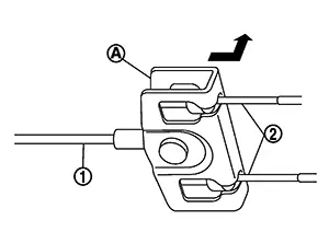
CAUTION:
To prevent damage to parts, do not bend the parking brake cables.
Remove the nuts from the parking brake lever assembly. Refer to Exploded View.
Disconnect the harness connector from the parking brake switch.
Remove the parking brake lever assembly.
INSTALLATION
Installation is in the reverse order of removal.
-
Perform the adjustment. Refer to Adjustment.
-
Perform the inspection. Refer to Inspection.
CAUTION:
Do not reuse the adjusting nut if the nut is removed.
Parking Brake Front Cable
Removal and Installation
Removal and Installation
REMOVAL
Remove the cup holder finisher. Refer to Exploded View.
Remove the
adjusting nut (A).
CAUTION:
Do not reuse the adjusting nut.
Pull the
equalizer (A) in the rearward direction and then in the upward
direction in order to separate the rear parking brake cables [LH/RH
(2)] from the front parking brake cable (1).
CAUTION:
To prevent damage to parts, do not bend the parking brake cables.
Remove the front parking brake cable. Refer to Exploded View.
INSTALLATION
Installation is in the reverse order of removal.
-
Perform the adjustment. Refer to Adjustment.
-
Perform the inspection. Refer to Inspection.
CAUTION:
Do not reuse the adjusting nut.
Parking Brake Rear Cable
Removal and Installation
Removal and Installation
REMOVAL
Remove the cup holder finisher. Refer to Exploded View.
Loosen the
adjusting nut (A).
CAUTION:
Do not reuse the adjusting nut if the nut is removed.
Note:
It is not necessary to remove the front parking brake cable.
Pull the
equalizer (A) in the rearward direction and then in the upward
direction in order to separate the rear parking brake cables [LH/RH
(2)] from the front parking brake cable (1).
CAUTION:
To prevent damage to parts, do not bend the parking brake cables.
Remove the rear under cover (LH/RH). Refer to Removal and Installation.
Reposition the exhaust heat insulator.
Remove the rear parking brake cable from the underbody bracket.
Separate the rear parking brake cable from the toggle lever. Refer to Exploded View.
Remove the bolts from the rear parking brake cable. Refer to Exploded View.
Remove the rear parking brake cable from the Nissan Sentra vehicle.
INSTALLATION
Installation is in the reverse order of removal.
-
Perform the adjustment. Refer to Adjustment.
-
Perform the inspection. Refer to Inspection.
CAUTION:
Do not reuse the adjusting nut if the nut is removed.
Parking Brake Switch
Removal and Installation
Removal and Installation
REMOVAL
Remove the cup holder finisher. Refer to Exploded View.
Disconnect the harness connector from the parking brake switch.
Remove the screw and the parking brake switch. Refer to Exploded View.
INSTALLATION
Installation is in the reverse order of removal.
CAUTION:
Replace the parking brake switch if it has been dropped or sustained an impact.
Service Data and Specifications (sds). Service Data and Specifications (sds). Service Data and Specifications (sds)
Parking Brake Control
Parking Brake Control
|
Item |
Standard |
|---|---|
|
Number of notches [under force of 196 N (20.0 kg-f, 44.1 lb-f)] |
8 − 9 notches |
|
Number of notches when brake warning lamp turns ON |
1 notch |
Other materials:
Removal and Installation
Combination Meter
Exploded View
Exploded View
1.
Front cover
2.
Combination meter
...
Remote Keyless Entry Function
System Diagram
System Diagram
System Description
System Description
The Intelligent Key has the same functions as the
remote control entry system. Therefore, it can be used in the same
manner as the remote controller by operating the door lock/unlock
button.
OPERATION
Re ...
Adas Control Unit 2
List of Ecu Reference
List of ECU Reference
ECU
Reference
ADAS control unit 2
Values On The Diagnosis Tool
...