Nissan Sentra Service Manual: P1650 Starter motor relay 2
Description
ECM controls ON/OFF state of the starter relay, according to the engine and vehicle condition. ECM transmits a control signal to IPDM E/R via BCM by CAN communication.
Under normal conditions, ECM controls and maintains the starter relay in OFF state during following condition:
- Engine is running.
- Selector lever is D position.
When detecting a decrease in engine speed due to rapid deceleration or heavy load condition, ECM controls and reactivates the starter relay.
IPDM E/R detects a control state of starter relay and starter control relay and transmits a feedback signal to ECM via CAN communication.
DTC Logic
DTC DETECTION LOGIC
NOTE:
- If DTC P1650 is displayed with DTC U1001, perform the trouble diagnosis for DTC U1001. Refer to EC-169, "DTC Logic".
- If DTC P1650 is displayed with DTC P0607, perform the trouble diagnosis for DTC P0607. Refer to EC-350, "Diagnosis Procedure".
| DTC No. | CONSULT screen terms (Trouble diagnosis content) | DTC detecting condition | Possible cause | |
| P1650 | STR MTR RELAY 2 (Starter motor relay 2) | A | Starter relay is stuck ON. |
|
| B | Starter relay power supply circuit is excessively high voltage. |
|
||
| C | Starter relay circuit is excessively low voltage |
|
||
DTC CONFIRMATION PROCEDURE
1.PRECONDITIONING
If DTC Confirmation Procedure has been previously conducted, always perform the following procedure before conducting the next test
- Turn ignition switch OFF and wait at least 10 seconds.
- Turn ignition switch ON.
- Turn ignition switch OFF and wait at least 10 seconds.
>> GO TO 2.
2.PERFORM DTC CONFIRMATION PROCEDURE FOR MALFUNCTION A AND C
- Turn ignition switch OFF and wait at least 10 seconds.
- Turn ignition switch ON.
- Turn ignition switch OFF and wait at least 10 seconds.
- Check 1st trip DTC.
Is 1st trip DTC detected? YES >> Proceed to EC-400, "Diagnosis Procedure".
NO >> GO TO 3.
3.PERFORM DTC CONFIRMATION PROCEDURE FOR MALFUNCTION B
 With CONSULT
CAUTION:
Always drive at a safe speed.
- Start the engine.
- Turn ignition switch OFF and wait at least 10 seconds.
- Turn ignition switch ON.
- Start the engine and warm it up to normal operating temperature.
- Turn ignition switch OFF.
- Lift up drive wheels.
- Turn ignition switch ON.
- Select “POWER BALANCE” in “ACTIVE TEST” mode of “ENGINE” using CONSULT.
- Restart the engine and let it idle at least 10 seconds.
- Shift the selector lever to D position while depressing fully the brake pedal.
- Select 1 - 4 cylinders in “POWER BALANCE” and cut the fuel of all cylinders.
- Check 1st trip DTC.
 Without CONSULT
CAUTION:
Always drive at a safe speed.
- Start the engine.
- Turn ignition switch OFF and wait at least 10 seconds.
- Turn ignition switch ON.
- Start the engine and warm it up to normal operating temperature.
- Turn ignition switch OFF.
- Lift up drive wheels
- Restart the engine and let it idle at least 10 seconds
- For CVT models: Shift the selector lever to D position while depressing
fully the brake pedal.
For M/T models: Fully release the clutch pedal.
- Disconnect vacuum hoses from intake manifold.
- Check 1st trip DTC.
Is 1st trip DTC detected? YES >> Proceed to EC-400, "Diagnosis Procedure".
NO >> INSPECTION END
Diagnosis Procedure
1.CHECK SELF-DIAGNOSTIC RESULT IN BCM
 With CONSULT
Check self-diagnostic result in BCM.
Are any DTC detected? YES >> Check the DTC. Refer to PCS-20, "DTC Index" (with intelligent key), PCS-48, "DTC Index" (without intelligent key).
NO >> GO TO 2.
2.CHECK SELF-DIAGNOSTIC RESULT IN IPDM E/R
 With CONSULT
Check self-diagnostic result in IPDM E/R.
Are any DTC detected? YES >> Check the DTC. Refer to BCS-49, "DTC Index" (with intelligent key), BCS-109, "DTC Index" (without intelligent key).
NO >> GO TO 3.
3.CHECK STARTER RELAY POWER SUPPLY CIRCUIT
Check the starter motor relay power supply circuit. Refer to PCS-29, "Diagnosis Procedure" (with intelligent key), or PCS-57, "Diagnosis Procedure" (without intelligent key).
Is the inspection result normal? YES >> GO TO 4.
NO >> Repair or replace error-detected parts.
4.CHECK STARTER RELAY CONTROL SIGNAL CIRCUIT
- Turn ignition switch OFF.
- Disconnect IPDM E/R harness connector.
- Disconnect ECM harness connector.
- Check the continuity between IPDM E/R harness connector and ECM harness connector.
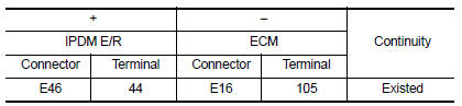
- Also check harness for short to ground to power.
Is the inspection result normal? YES >> GO TO 5.
NO >> Repair or replace error-detected parts.
5.CHECK INTERMITTENT INCIDENT
Check intermittent incident. Refer to GI-39, "Intermittent Incident".
Is the inspection result normal? YES >> Replace IPDM E/R. Refer to PCS-30, "Removal and Installation".
NO >> Repair or replace error-detected parts.
 P1574 ASCD Vehicle speed sensor
Description
The ECM receives two vehicle speed sensor signals via CAN communication line.
One is sent from combination
meter, and the other is from TCM (Transmission control module). The ECM uses ...
 P1651 Starter motor relay
Description
ECM controls ON/OFF state of the starter relay, according to the engine and
vehicle condition. ECM transmits
a control signal to IPDM E/R by CAN communication.
Under normal conditio ...
Other materials:
C1120, C1122, C1124, C1126 ABS In valve system
DTC Logic
Dtc detection logic
DTC
Display Item
Malfunction detected condition
Possible causes
C1120
FR LH IN ABS SOL
When a malfunction is detected in front LH ABS IN
valve.
Harness or connector
ABS actuator and electric unit
(control unit)
...
Removal and installation
Audio unit
Exploded view
Audio unit
Audio unit bracket (LH)
Audio unit bracket (RH)
Removal and installation
Removal
Disconnect the negative battery terminal. Refer to pg-50, "removal and
installation (battery)".
Remove cluster lid c lower. Refer to ip-20, "re ...
Electric oil pump
Exploded View
Transaxle assembly
Electric oil pump sub harness
O-ring
Electric oil pump and motor assembly
CVT fluid
Removal and Installation
REMOVAL
Remove neighboring parts of electric oil pump.
Remove electric oil pump sub harness.
Remove electric oil pump and motor a ...
