Nissan Sentra Service Manual: P1564 ASCD Steering switch
DTC Logic
DTC DETECTION LOGIC
NOTE:
If DTC P1564 is displayed with DTC P0605, first perform the trouble diagnosis for DTC P0605. Refer to EC-348, "DTC Logic".
| DTC No. | CONSULT screen terms (Trouble diagnosis content) | DTC detecting condition | Possible cause |
| P1564 | ASCD SW (ASCD SW) |
|
|
DTC CONFIRMATION PROCEDURE
1.PRECONDITIONING
If DTC Confirmation Procedure has been previously conducted, always perform the following procedure before conducting the next test.
- Turn ignition switch OFF and wait at least 10 seconds.
- Turn ignition switch ON
- Turn ignition switch OFF and wait at least 10 seconds.
>> GO TO 2.
2.PERFORM DTC CONFIRMATION PROCEDURE
- Turn ignition switch ON.
- Wait at least 10 seconds.
- Press MAIN switch for at least 10 seconds, then release it and wait at least 10 seconds.
- Press CANCEL switch for at least 10 seconds, then release it and wait at least 10 seconds.
- Press ACCEL/RES switch for at least 10 seconds, then release it and wait at least 10 seconds.
- Press COAST/SET switch for at least 10 seconds, then release it and wait at least 10 seconds.
- Check DTC.
Is DTC detected? YES >> Proceed to EC-388, "Diagnosis Procedure".
NO >> INSPECTION END
Diagnosis Procedure
1.CHECK ASCD STEERING SWITCH CIRCUIT
 With CONSULT
- Turn ignition switch ON.
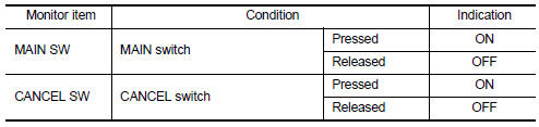
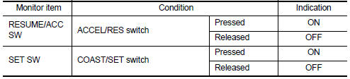
- Select “CANCEL SW”, “RESUME/ACC SW” and “SET SW” in “DATA MONITOR” mode of “ENGINE” using CONSULT.
- Check each item indication as per the following conditions.
 Without CONSULT
- Turn ignition switch ON.
- Check the voltage between ECM harness connector terminals.
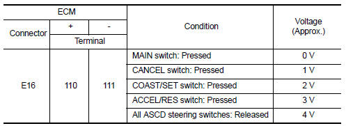
Is the inspection result normal? YES >> Check intermittent incident. Refer to GI-39, "Intermittent Incident".
NO >> GO TO 2.
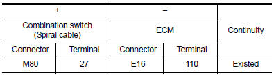
2.CHECK ASCD STEERING SWITCH GROUND CIRCUIT
- Turn ignition switch OFF.
- Disconnect ECM harness connector.
- Disconnect combination switch (spiral cable) harness connector
- Check the continuity between combination switch (spiral cable) and ECM harness connector.
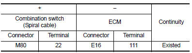
- Also check harness for short to ground and to power.
Is the inspection result normal? YES >> GO TO 3.
NO >> Repair or replace error-detected parts.
3.CHECK ASCD STEERING SWITCH INPUT SIGNAL CIRCUIT
- Check the continuity between ECM harness connector and combination switch.
- Also check harness for short to ground and to power.
Is the inspection result normal? YES >> GO TO 4.
NO >> Repair or replace error-detected parts.
4.CHECK ASCD STEERING SWITCH
Refer to EC-390, "Component Inspection".
Is the inspection result normal? YES >> Check intermittent incident. Refer to GI-39, "Intermittent Incident".
NO >> Replace ASCD steering switch. Refer to EC-15, "ENGINE CONTROL SYSTEM : Component Parts Location".
Component Inspection
1.CHECK ASCD STEERING SW
- Disconnect combination switch (spiral cable) harness connector.
- Check the resistance between combination switch harness connector terminals as per the following conditions.
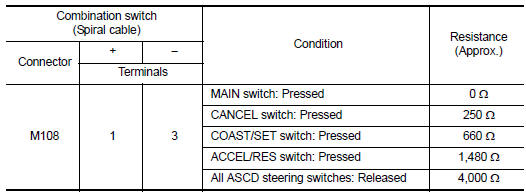
Is the inspection result normal? YES >> INSPECTION END
>> Replace ASCD steering switch. Refer to EC-15, "ENGINE CONTROL SYSTEM : Component Parts Location".
 P1556, P1557 Battery temperature sensor
DTC Logic
DTC DETECTION LOGIC
NOTE:
If DTC P1556 or P1557 is displayed with DTC P0643, first perform the
trouble diagnosis for DTC P0643.
Refer to EC-353, "DTC Logic".
DTC No ...
 P1572 ASCD Brake switch
DTC Logic
DTC DETECTION LOGIC
NOTE:
If DTC P1572 is displayed with DTC P0605, first perform the trouble
diagnosis for DTC P0605. Refer
to EC-348, "DTC Logic".
This self-diagnosi ...
Other materials:
Seat belt warning system
Seat Belt Warning System Does Not Function
1.SEAT BELT WARNING LIGHT
Turn ignition switch ON.
Does the seat belt warning lamp come ON?
YES >> GO TO 2.
NO >> • Check 10A fuse [No. 8, located in the fuse block (J/B)].
Check seat belt buckle switch (driver seat)
Check ha ...
P0605 ECM
DTC Logic
DTC DETECTION LOGIC
DTC No.
CONSULT screen terms
(Trouble diagnosis content)
DTC detecting condition
Possible cause
P0605
ECM
[Internal control module
read only memory (ROM)
error]
Malfunction in the internal ROM of ECM.
ECM
DTC CONFIRM ...
Rear bumper
Exploded view
Rear bumper side bracket (LH)
Rear bumper reinforcement
Rear bumper energy absorber
Rear bumper fascia reflector (LH)
Rear bumper fascia reflector (RH)
Rear bumper fascia
Rear bumper side bracket (RH)
Pawl
Removal and installation
CAUTION:
Bumper fascia is ma ...
