Nissan Sentra Service Manual: P0712 Transmission fluid temperature sensor A
DTC Logic
DTC DETECTION LOGIC
| DTC | CONSULT screen terms (Trouble diagnosis content) | DTC detection condition | Possible causes |
| P0712 | FLUID TEMP SENSOR A (Transmission Fluid Temperature Sensor A Circuit Low) | The CVT fluid temperature identified by the
TCM is 180В°C (356В°F) or more continuously
for 5 seconds or more under the following diagnosis
conditions: Diagnosis conditions
|
|
DTC CONFIRMATION PROCEDURE
1.PREPARATION BEFORE WORK
If another “DTC CONFIRMATION PROCEDURE” occurs just before, turn ignition switch OFF and wait for at least 10 seconds, then perform the next test.
>> GO TO 2.
2.PERFORM DTC CONFIRMATION PROCEDURE
- Start the engine and wait for 10 seconds or more.
- Check the first trip DTC.
Is “P0712” detected? YES >> Go to TM-174, "Diagnosis Procedure".
NO >> INSPECTION END
Diagnosis Procedure
1.CHECK CIRCUIT BETWEEN TCM AND CVT UNIT
- Turn ignition switch OFF.
- Disconnect TCM connector and CVT unit connector.
- Check continuity between TCM harness connector terminal and ground.
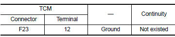
Is the inspection result normal? YES >> GO TO 2.
NO >> Repair or replace malfunctioning part.
2.CHECK CVT FLUID TEMPERATURE SENSOR
Check CVT fluid temperature sensor. Refer to TM-174, "Component Inspection".
Is the inspection result normal? YES >> Check intermittent incident. Refer to GI-39, "Intermittent Incident".
NO >> Repair or replace malfunctioning parts.
Component Inspection
1.CHECK CVT FLUID TEMPERATURE SENSOR
Check resistance between CVT unit connector terminals.
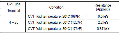
Is the inspection result normal? YES >> INSPECTION END
NO >> There is a malfunction of CVT fluid temperature sensor. Replace transaxle assembly. Refer to TM-283, "Removal and Installation".
 P0711 Transmission fluid temperature sensor A
DTC Logic
DTC DETECTION LOGIC
DTC
CONSULT screen terms
(Trouble diagnosis content)
DTC detection condition
Possible causes
P0711
FLUID TEMP SENSOR A
(Transmission F ...
 P0713 Transmission fluid temperature sensor A
DTC Logic
DTC DETECTION LOGIC
DTC
CONSULT screen terms
(Trouble diagnosis content)
DTC detection condition
Possible causes
P0713
FLUID TEMP SENSOR A
(Transmission ...
Other materials:
Symptom diagnosis
Nissan vehicle immobilizer systemnats
symptoms
Symptom Table
Note:
Before performing the diagnosis in the following table, check
“SEC-171, "Work Flow"”.
Check that vehicle is under the condition shown in “Conditions of
vehicle” before starting diagnosis, ...
Precaution for Supplemental Restraint System (SRS) "AIR BAG" and "SEAT BELT
PRE-TENSIONER"
The Supplemental Restraint System such as “AIR BAG” and “SEAT BELT PRE-TENSIONER”,
used along
with a front seat belt, helps to reduce the risk or severity of injury to the
driver and front passenger for certain
types of collision. Information necessary to service the system ...
Latch system for children
Exploded View
LATCH bracket (RH)
LATCH bracket (LH)
Seat belt buckle anchor bracket
Front
Removal and Installation
REMOVAL
Remove the rear seat cushion assembly. Refer to SE-23, "Removal and
Installation - Seat Cushion
Assembly"
Remove the rear seatback assemb ...
