Nissan Sentra Service Manual: P0139 HO2S2
DTC Logic
DTC DETECTION LOGIC
The heated oxygen sensor 2 has a much longer switching time between rich and lean than the air fuel ratio (A/F) sensor 1. The oxygen storage capacity of the three way catalyst 1 causes the longer switching time. To judge the malfunctions of heated oxygen sensor 2, ECM monitors whether the switching response of the sensor's voltage is faster than specified during various driving conditions such as fuel cut.
| DTC No. | CONSULT screen terms (Trouble diagnosis content) | DTC detecting condition | Possible cause |
| P0139 | HO2S2 (B1) (O2 sensor circuit slow response bank 1 sensor 2) | The switching time between rich and lean of a heated oxygen sensor 2 signal delays more than the specified time computed by ECM. |
|
DTC CONFIRMATION PROCEDURE
1.INSPECTION START
Do you have CONSULT? Do you have CONSULT? YES >> GO TO 2.
NO >> GO TO 6.
2.PRECONDITIONING
If DTC Confirmation Procedure has been previously conducted, always perform the following procedure before conducting the next test.
- Turn ignition switch OFF and wait at least 10 seconds.
- Turn ignition switch ON
- Turn ignition switch OFF and wait at least 10 seconds.
TESTING CONDITION:
For better results, perform “DTC WORK SUPPORT” at a temperature of 0 to 30°C (32 to 86°F).
>> GO TO 3.
3.PERFORM DTC CONFIRMATION PROCEDURE
 With CONSULT
- Start engine and warm it up to the normal operating temperature.
- Turn ignition switch OFF and wait at least 10 seconds.
- Turn ignition switch ON.
- Turn ignition switch OFF and wait at least 10 seconds.
- Start engine and keep the engine speed between 3,500 and 4,000 rpm for at least 1 minute under no load.
- Let engine idle for 1 minute.
- Select “DATA MONITOR” mode of “ENGINE” using CONSULT.
- Make sure that “COOLANT TEMP/S” indicates more than 70°C (158°F).
If not, warm up engine and go to next step when “COOLANT TEMP/S” indication reaches to 70°C (158°F).
- Open engine hood.
- Select “HO2S2 (B1) P0139” in “DTC WORK SUPPORT” mode of “ENGINE” using CONSULT.
- Start engine and follow the instruction of CONSULT display.
NOTE:
It will take at most 10 minutes until “COMPLETED” is displayed.
Is “COMPLETED” displayed on CONSULT screen? YES >> GO TO 5.
NO >> GO TO 4.
4.PERFORM DTC CONFIRMATION PROCEDURE AGAIN
- Turn ignition switch OFF and leave the vehicle in a cool place (soak the vehicle).
- Perform DTC confirmation procedure again.
>> GO TO 3.
5.PERFORM SELF-DIAGNOSIS
 With CONSULT
Perform ECM self-diagnosis.
Is DTC “P0139” detected? YES >> Proceed to EC-234, "Diagnosis Procedure".
NO >> INSPECTION END
6.PERFORM COMPONENT FUNCTION CHECK
Perform component function check. Refer to EC-233, "Component Function Check".
NOTE:
Use component function check to check the overall function of the heated oxygen sensor 2 circuit. During this check, a 1st trip DTC might not be confirmed.
Is the inspection result normal? YES >> INSPECTION END
NO >> Proceed to EC-234, "Diagnosis Procedure".
Component Function Check
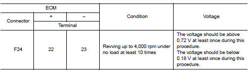
1.PERFORM COMPONENT FUNCTION CHECK-1
 Without CONSULT
- Start engine and warm it up to normal operating temperature.
- Turn ignition switch OFF and wait at least 10 seconds.
- Start engine and keep the engine speed between 3,500 and 4,000 rpm for at least 1 minute under no load.
- Let engine idle for 1 minute.
- Check the voltage between ECM harness connector and ground as per the following condition.
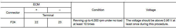
Is the inspection result normal? YES >> INSPECTION END
NO >> GO TO 2.
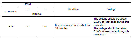
2.PERFORM COMPONENT FUNCTION CHECK-2
Check the voltage between ECM harness connector and ground as per the following condition.
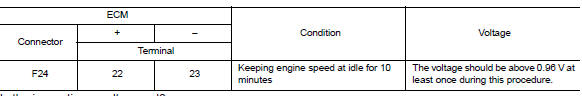
Is the inspection result normal? YES >> INSPECTION END
NO >> GO TO 3.
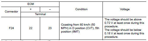
3.PERFORM COMPONENT FUNCTION CHECK-3
Check the voltage between ECM harness connector and ground as per the following condition.
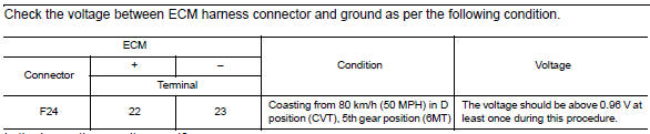
Is the inspection result normal? YES >> INSPECTION END
NO >> Proceed to EC-234, "Diagnosis Procedure".
Diagnosis Procedure
1.CLEAR THE MIXTURE RATIO SELF-LEARNING VALUE
- Clear the mixture ratio self-learning value. Refer to EC-142, "Work Procedure".
- Run engine for at least 10 minutes at idle speed.
Is the 1st trip DTC P0171 or P0172 detected? Is it difficult to start engine? YES >> • Perform trouble diagnosis for DTC P0171. Refer to EC-246, "DTC Logic".
• Perform trouble diagnosis for DTC P0172. Refer to EC-250, "DTC Logic".
NO >> GO TO 2.
2.CHECK HO2S2 GROUND CIRCUIT
- Turn ignition switch OFF.
- Disconnect heated oxygen sensor 2 harness connector.
- Disconnect ECM harness connector.
- Check the continuity between HO2S2 harness connector and ECM harness connector.
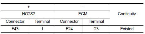
- Also check harness for short to power.
Is the inspection result normal? YES >> GO TO 3.
NO >> Repair or replace error-detected parts.
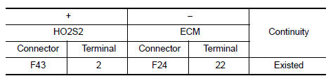
3.CHECK HO2S2 INPUT SIGNAL CIRCUIT
- Check the continuity between HO2S2 harness connector and ECM harness connector.
- Check the continuity between HO2S2 harness connector and ground, or ECM harness connector and ground.
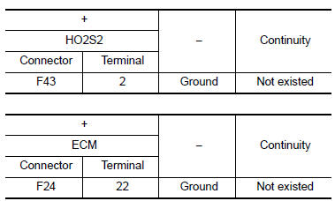
- Also check harness for short to power.
Is the inspection result normal? YES >> GO TO 4.
NO >> Repair or replace error-detected parts.
4.CHECK HEATED OXYGEN SENSOR 2
Check the heated oxygen sensor 2. Refer to EC-235, "Component Inspection (HO2S2)".
Is the inspection result normal? YES >> Check intermittent incident. Refer to GI-39, "Intermittent Incident".
NO >> Replace heated oxygen sensor 2. Refer to EX-5, "Exploded View".
Component Inspection (HO2S2)
1.INSPECTION START
Do you have CONSULT? Do you have CONSULT? YES >> GO TO 2.
NO >> GO TO 3.
2.CHECK HEATED OXYGEN SENSOR 2
 With CONSULT
- Turn ignition switch ON and select “DATA MONITOR” mode of “ENGINE” using CONSULT.
- Start engine and warm it up to normal operating temperature.
- Turn ignition switch OFF and wait at least 10 seconds.
- Start engine and keep the engine speed between 3,500 and 4,000 rpm for at least 1 minute under no load.
- Let engine idle for 1 minute.
- Select “FUEL INJECTION” in “ACTIVE TEST” mode of “ENGINE” using CONSULT, and select “HO2S2 (B1)” as the monitor item with CONSULT.
- Check “HO2S2 (B1)” at idle speed when adjusting “FUEL INJECTION” to ± 25%.
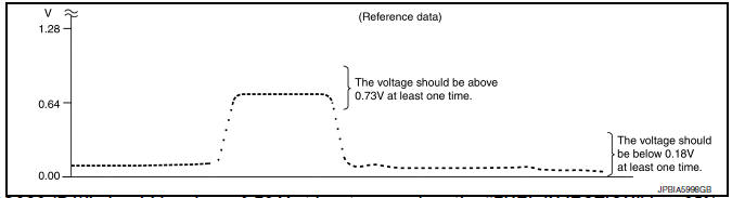
“HO2S2 (B1)” should be above 0.72 V at least once when the “FUEL INJECTION” is + 25%.
“HO2S2 (B1)” should be below 0.18 V at least once when the “FUEL INJECTION” is − 25%.
Is the inspection result normal? YES >> INSPECTION END
NO >> Replace heated oxygen sensor 2. Refer to EX-5, "Exploded View".
3.CHECK HEATED OXYGEN SENSOR 2-1
 Without CONSULT
- Start engine and warm it up to normal operating temperature.
- Turn ignition switch OFF and wait at least 10 seconds.
- Start engine and keep the engine speed between 3,500 and 4,000 rpm for at least 1 minute under no load.
- Let engine idle for 1 minute.
- Check the voltage between ECM harness connector and ground as per the following condition.
Is the inspection result normal? YES >> INSPECTION END
NO >> GO TO 4.
4.CHECK HEATED OXYGEN SENSOR 2-2
Check the voltage between ECM harness connector and ground as per the following condition.
Is the inspection result normal? YES >> INSPECTION END
NO >> GO TO 5.
5.CHECK HEATED OXYGEN SENSOR 2-3
Check the voltage between ECM harness connector and ground as per the following condition.
Is the inspection result normal? YES >> INSPECTION END
NO >> Replace heated oxygen sensor 2. Refer to EX-5, "Exploded View".
 P0138 HO2S2
DTC Logic
DTC DETECTION LOGIC
The heated oxygen sensor 2 has a much longer switching time between rich and
lean than the air fuel ratio (A/
F) sensor 1. The oxygen storage capacity of the three w ...
 P014C, P014D, P015A, P015B A/F Sensor 1
DTC Logic
DTC DETECTION LOGIC
To judge the malfunction of A/F sensor 1, this diagnosis measures response
time of the A/F signal computed
by ECM from the A/F sensor 1 signal. The time is compensat ...
Other materials:
Electrical units location
Electrical units location
Engine compartment
Passenger compartment
Luggage compartment
...
Tightening Torque Table (New Standard Included)
CAUTION:
The special parts are excluded.
The bolts/nuts in these tables have a strength (discrimination)
number/symbol assigned to the head
or the like. As to the relation between the strength grade in these tables
and the strength (discrimination)
number/symbol, refer to “DISCR ...
Heater and Air Conditioner (manual) (if so equipped)
WARNING
The air conditioner cooling function operates
only when the engine is running.
Do not leave children or adults who would
normally require the assistance of others
alone in your vehicle. Pets should also not
be left alone. They could accidentally injure
them ...
