Nissan Sentra Service Manual: P0011 IVT control
DTC Logic
DTC DETECTION LOGIC
NOTE:
If DTC P0011 is displayed with DTC P0075, first perform the trouble diagnosis for EC-180, "DTC Logic".
| DTC No. | CONSULT screen terms (Trouble diagnosis content) | DTC detecting condition | Possible cause |
| P0011 | INT/V TIM CONT-B1 (″A″ Camshaft position - timing over-advanced or system performance bank 1) | There is a gap between angle of target and phase-control angle degree. |
|
DTC CONFIRMATION PROCEDURE
1.PRECONDITIONING
If DTC Confirmation Procedure has been previously conducted, always perform the following procedure before conducting the next test.
- Turn ignition switch OFF and wait at least 10 seconds.
- Turn ignition switch ON.
- Turn ignition switch OFF and wait at least 10 seconds.
TESTING CONDITION:
Before performing the following procedure, confirm that battery voltage is between 11 V and 16 V at idle.
>> GO TO 2.
2.PERFORM DTC CONFIRMATION PROCEDURE-1
 With CONSULT
- Turn ignition switch ON and select “DATA MONITOR” mode of “ENGINE” using CONSULT
- Start engine and warm it up to normal operating temperature.
- Maintain the following conditions for at least 6 consecutive seconds. Hold the accelerator pedal as steady as possible.
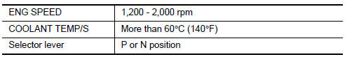
- Stop vehicle with engine running and let engine idle for 10 seconds.
- Check 1st trip DTC.
 With GST
Follow the procedure “With CONSULT” above.
Is 1st trip DTC detected? YES >> Proceed to EC-171, "Diagnosis Procedure".
NO >> GO TO 3.
3.PERFORM DTC CONFIRMATION PROCEDURE-2
 With CONSULT
- Maintain the following conditions for at least 20 consecutive seconds.
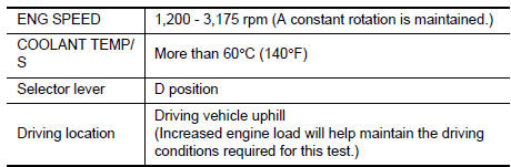
CAUTION:
Always drive at a safe speed.
- Check 1st trip DTC.
 With GST
Follow the procedure “With CONSULT” above.
Is 1st trip DTC detected? YES >> Proceed to EC-171, "Diagnosis Procedure".
NO >> INSPECTION END
Diagnosis Procedure
1.CHECK OIL PRESSURE WARNING LAMP
- Start engine.
- Check oil pressure warning lamp and confirm it is not illuminated.
Is oil pressure warning lamp illuminated? YES >> Check the engine oil level. Refer to LU-7, "Inspection".
NO >> GO TO 2.
2.CHECK INTAKE VALVE TIMING CONTROL SOLENOID VALVE
Check the intake valve timing control solenoid valve. Refer to EC-172, "Component Inspection".
Is the inspection result normal? YES >> GO TO 3.
NO >> Replace intake valve timing control solenoid valve. Refer to EM-48, "Exploded View".
3.CHECK CRANKSHAFT POSITION SENSOR (POS)
Check the crankshaft position sensor (POS). Refer to EC-279, "Component Inspection [CKP Sensor (POS)]".
Is the inspection result normal? YES >> GO TO 4.
NO >> Replace crankshaft position sensor (POS). Refer to EM-33, "Exploded View".
4.CHECK CAMSHAFT POSITION SENSOR (PHASE)
Check the camshaft position sensor (PHASE). Refer to EC-282, "Component Inspection [CMP Sensor (PHASE)]".
Is the inspection result normal? YES >> GO TO 5.
NO >> Replace camshaft position sensor (PHASE). Refer to EM-60, "Exploded View".
5.CHECK CAMSHAFT (INT)
Check the following.
- Accumulation of debris to the signal plate of camshaft rear end
- Chipping signal plate of camshaft rear end
Is the inspection result normal? YES >> GO TO 6.
NO >> Remove debris and clean the signal plate of camshaft rear end or replace camshaft. Refer to EM-60, "Removal and Installation".
6.CHECK TIMING CHAIN INSTALLATION
Check service records for any recent repairs that may cause timing chain misaligned.
Are there any service records that may cause timing chain misaligned? YES >> Check timing chain installation. Refer to EM-49, "Removal and Installation".
NO >> GO TO 7.
7.CHECK LUBRICATION CIRCUIT
Refer to LU-7, "Inspection", “INSPECTION AFTER INSTALLATION”.
Is the inspection result normal? YES >> Check intermittent incident. Refer to GI-39, "Intermittent Incident".
NO >> Clean lubrication line.
Component Inspection
1.CHECK INTAKE VALVE TIMING CONTROL SOLENOID VALVE-1
- Turn ignition switch OFF.
- Disconnect intake valve timing control solenoid valve harness connector.
- Check resistance between intake valve timing control solenoid valve terminals as per the following.
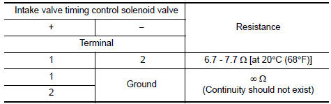
Is the inspection result normal? YES >> GO TO 2.
NO >> Replace intake valve timing control solenoid valve. Refer to EM-48, "Exploded View".
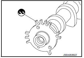
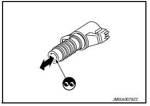
2.CHECK INTAKE VALVE TIMING CONTROL SOLENOID VALVE-2
- Remove intake valve timing control solenoid valve. Refer to EM-48, "Exploded View".
- Provide 12 V DC between intake valve timing control solenoid valve terminals 1 and 2, and then interrupt it. Make sure that the plunger moves as shown in the figure.
CAUTION:
Do not apply 12 V DC continuously for 5 seconds or more.
Doing so may result in damage to the coil in intake valve timing control solenoid valve.
NOTE:
Always replace O-ring when intake valve timing control solenoid valve is removed.
Is the inspection result normal? YES >> INSPECTION END
NO >> Replace intake valve timing control solenoid valve. Refer to EM-48, "Exploded View".
 U1001 can comm circuit
Description
CAN (Controller Area Network) is a serial communication line for real time
application. It is an on-vehicle multiplex
communication line with high data communication speed and excellen ...
 P0014 EVT control
DTC Logic
DTC DETECTION LOGIC
NOTE:
If DTC P0014 is displayed with DTC P0078, first perform trouble
diagnosis for DTC P0078. Refer to
EC-183, "DTC Logic".
If DTC P0014 is displa ...
Other materials:
Precautions when starting and driving
WARNING
Do not leave children or adults who
would normally require the assistance
of others alone in your vehicle. Pets
should also not be left alone. They
could accidentally injure themselves or
others through inadvertent operation of
the vehicle. Also, on hot, su ...
Water pump
Exploded View
Gasket
Water pump
WARNING:
Do not remove the radiator cap when the engine is hot. Serious burns
could occur from high-pressure
engine coolant escaping from the radiator. Wrap a thick cloth around the cap.
Slowly push down and
turn it a quarter turn to allow built-up ...
Rear parcel shelf finisher
Exploded View
Seat belt finisher (RH)
Rear parcel shelf finisher
Rear seatback finisher (RH)
Top tether strap anchor finisher
(RH)
Top tether strap anchor finisher
(center)
Rear seatback finisher (LH)
Top tether strap anchor finisher
(LH)
Seat belt finisher (LH)
Seat b ...
